The LAB Report
![]()
December 2025.
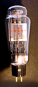
A 300B mesh version, fully compatible with standard 300B.
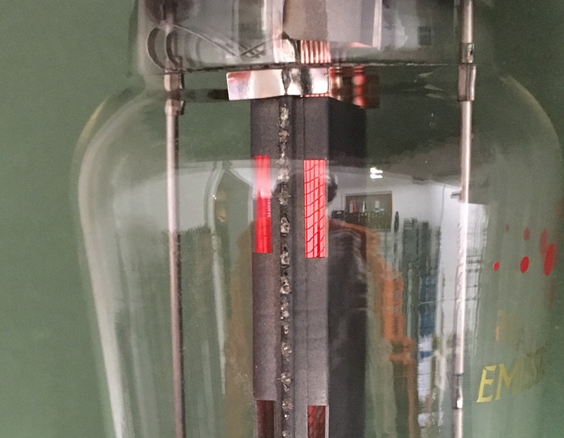
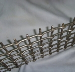 In the English dictionary, mesh refers to a woven, knit, or knotted material. It is not what the Chinese are doing, punch holes in a thin foil, giving you only the optical illusion. What is missing with a punched plate, is the damping properties of mesh. In industry, when a sheet of mesh wire is rolled, it gives an excellent mechanical damping device. We do not really know why mesh tubes sound better, but it may have to do with the good mechanical damping of the mesh. Also with the fact that a part of the electrons escape through the tiny holes, and from there land on the plate at the outside. They still contribute to the plate current that way, but the path of those is different. Finally, a very small fraction of those (it is really extremely little) land on the glass, causing the blue fluorescent effect which is seen often for mesh tubes. Anyway, we can only speculate why mesh tubes sound different.
 |
There are also some disadvantage of mesh wire too.
Mesh wire can not take as much heat as solid plates. We always made our 300B Mesh tubes with this limitation. But we have now reached a technological breakthrough. With our new technology, we can significantly increase the plate dissipation of our tubes. For 300B mesh version up to the same level as solid plate 300B.
What stays however, mesh tubes by nature have some more noise. This is not audible if they are used as output tubes, or as driver tubes for low gain output tubes. However the additional noise may become audible if used as pre-amplifier or as head phone amplifier. Use in such applications is not impossible, but to prevent problems, we do not recommend it.
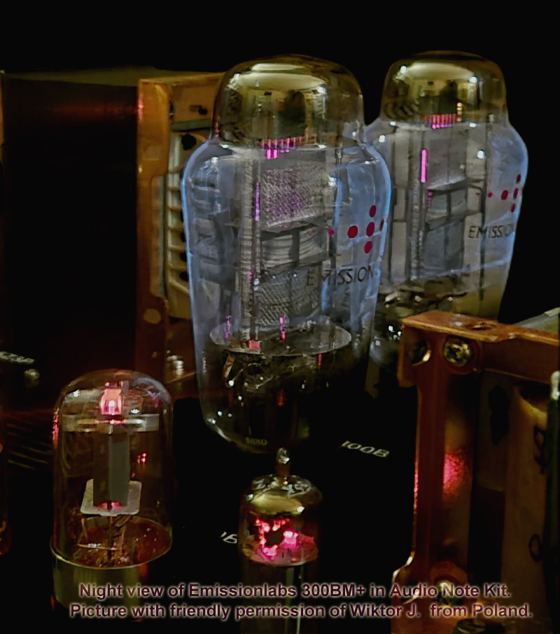
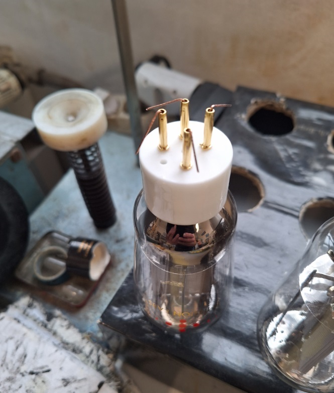
Our new 300B Mesh tube, we call it 300BM+. The "plus" stands for the plug and play capability with existing 300B loudspeaker amplifiers.
Product release is February 1st 2026.
July 2024. We will re issue RS242, as made by Telefunken during WW2.

Final prototypes, just now with UX4 base.
The RS242, like all Telefunken 'RS' tubes, was a transmitter tube. Curves, as we would have needed them for Audio Applications, were never published. Like most other transmitter triodes however, also RS242 works very good at low frequency. Famous examples of transmitter tubes, also used as Audio tubes, are the 845 and GM70, or the 304TL, just to mention some. The 845 data sheet even mentions the use as audio amplifier.
Saying RS242 works 'good' as an audio tube, is an understatement. The linearity of the curves is amazing. I was not aware, because those curves were never published. After making a curve plot with Audiomatica's Sofia curve tracer, from a pair of NOS RS242 tubes, I was so impressed by the linearity. Such a result is no coincidence, and I understood why this tube is so famous amongst Japanese DIY. The tube curve, and some more information, I published on a page at the jacmusic website, which is more general. If you are interested, just enter RS242 in the search box of the jacmusic website. This sparked some requests for RS242 NOS, but this tube is very hard to find in unused condition. Almost impossible.
Transmitter tubes however have also some disadvantages, which makes them not very easy to use for HiFi. They are intended for very high voltage, which means they are by nature high impedance devices. This high voltage, mostly in the kV range, makes the use of Barium Cathodes impossible. So they have Thoriated Tungsten cathodes. Such cathodes glow sure nicer, but their disadvantage is a significant lower ratio of emission to heater power, if compared to Barium cathodes. In a practical situation, this results in tubes which work very good at high voltage, low current, at quite high heater current. The drawback of a high impedance tube is, it works not good at low voltage, high current. If you do, the result is hardly any output power, and still a lot of dissipation. So the easiest to use transmitter tubes for HiFi, would be such that are MADE for low power applications, which is almost a contradiction by itself. Yes, they do exist, but they are not many.
Looking at the RS242, in a low power transmitter, what would the German military have needed that for in the year 1942? This is interesting, to look back on what they did. The answer can only be: For field operation. The requirements for field operation are clear: Such tubes must have low heater current, and low anode voltage, in order to use the available batteries of those days in a practical way. The heater supply was a sulfuric acid filled, lead battery, carried around in a back pack. Heavy and dangerous with respect to leakage. That acid will burn your skin badly if it is spilled. So a two-cell only 4.2V battery has less risk than than a three-cell 6.3V battery. 2.1V would have meant one cell only, but whatever the reason, most battery tubes seem to be 4.2V.
Production quantity of RS242 was low. I have a copy of the Telefunken factory papers. showing production was 1994 pcs in total, from 1940 to 1945. Before the war, it was not made, and after the war production of German military items was not allowed by the allies. So it is a miracle, that after almost a century, from 1994 pieces ever made, still some can be found, even in top condition.
December 2023. The making of RGN2504-Mesh.
On Ebay the original Telefunken RGN2504 mesh is achieving totally crazy prices above 2000 Euro.
The making of RGN 2504 at Emission Labs.
Here are some (incomplete) notes about the available part numbers of this family. Like all rectifiers, they are different in maximum current and maximum voltage. Like so often you don't get high current and high voltage at the same time. So tubes are usually made for high voltage, low current, or the the other way around. This 4Volt TFK family has the heater current and voltage in the part number, so RGN2004 has a 2A, 4V heater.
As always, there is this special club of tube lovers who prefer the 4Volt series tubes, for their superior sound. Note, the heater voltage of Telefunken is specified very tight, it is 3.8...4V, which is a difference of only +/-2.5%.
I think nobody has the original data sheets of the RGN tubes. Things which can be found is the RGN1064 from RTF, but it seems to me they specified it higher than Telefunken. We can not call this the official RGN1064 data sheet, as RFT copied the whole tube.
So what I know for sure, falls back to one original TKF overview sheet, I have. For the rest there are overviews around from general data book collections, but these are problematic, because they do not give the source, and risk is one person just made it up, and the others copied it.
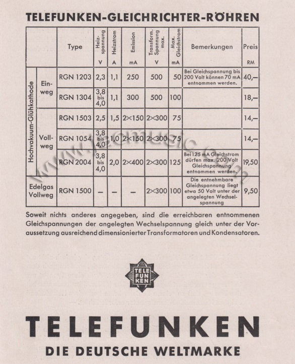
Some Data with Source
ACin |
DC Out |
First C |
Winding |
Source |
|
RGN2004 |
2x300V~ 2x500V~ |
160mA 125mA |
32uF | 2x 50Ohms 2x 30Ohms |
*1 |
RGN2504 |
2x500V~ | 180mA | *1 | ||
RGN4004 |
2x300V~ | 300mA | *1 |
*1 Source: Jürgen Schwandt. Röhrentaschentabelle, Francis Verlag.
From what is seems, RGN4004 was intended as a high current, medium voltage tube.
RGN2504 was the opposite, a high voltage medium current tube. It resembles 5U4G reasonably, but 5U4G seems slightly shifted more into direction of somewhat higher current, at somewhat lower voltage.
Whereas RGN2004 can do both, but general at lower current. Also this tube is heavily limited in DC voltage, it can be only 200VDC at maximum current of 125mA. Only at lower current, voltage may be higher. This is from an original Telefunken flyer (See above).
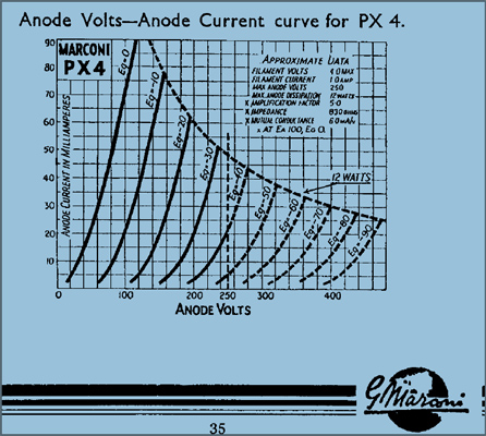
June 2023. The making of PX25.
Another member of the 4 Volt series. As all of these, admired for their unique sound.
When making the PX25, we had some a specific problems to solve. This is a similar situation as with PX4, which story is described here. The OSRAM data sheet consists of two parts. There is the tube curves, which of course is the genetic fingerprint of the tube. But there is also the text parts, which should describe how to use it, some tables with data, such as working points, and ways to test the tube. And here is where the situation becomes strange. PX25 was the first large triode of it's kind, designed by OSRAM England. The best tube tester at those days was the AVO "Two Panel" Valve Tester. This was a box, looking a bit like a large multi meter, which connected with a cable to another box, full of tube sockets. I had two of those in my collection, and despite being 100 years old (yes!) the worked totally perfect, giving correct transconductance values for 6SN7 or EL84. But here comes the drawback, this tester worked along the zero volt grid curve. Which is possible, and no problem to do, and it saves having to create a negative grid voltage, and prevented other issues too. Really a clever idea. BUT..... nobody uses this a working point in real amplifiers. Now, at zero volt on the control grid, tubes draw a lot of current, so they could use much lower anode voltage too. That makes the whole tester easier to build. So far, so good, and it works very reliable. Only, the usual test points for this have to be found out by the tube manufacturer, for and with the AVO "Two Panel" Valve Tester. Which is what they did at OSRAM.
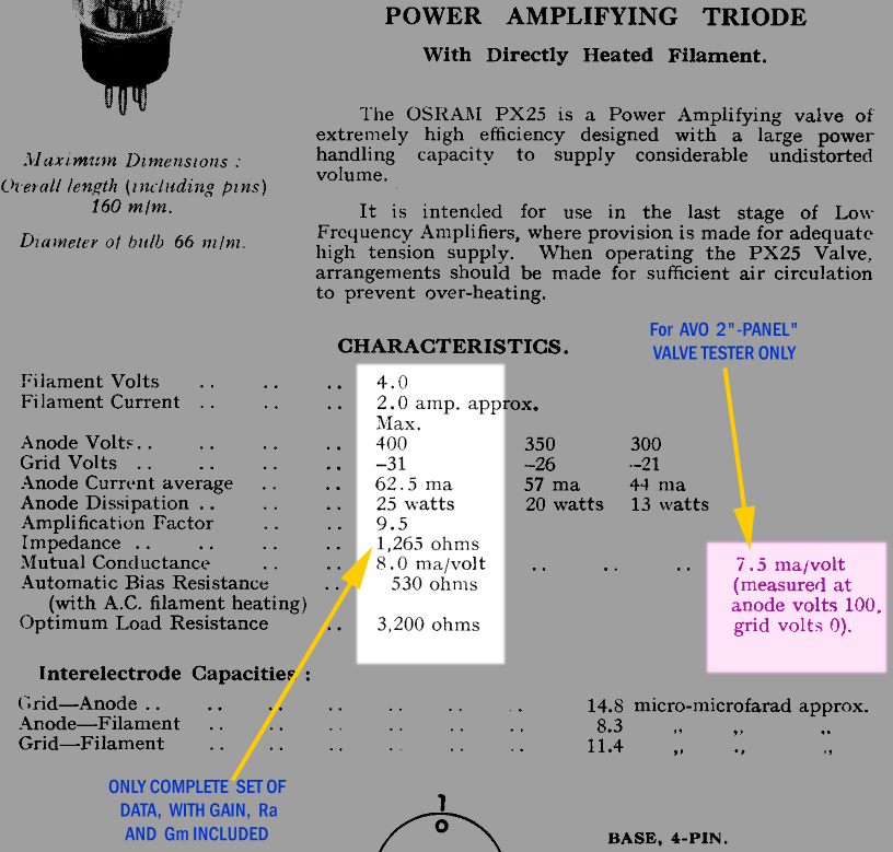
So you can see in there, the working point for the AVO tester:
Ua=100V and Ug=0V, which must result in 7.5mA/V transconductance. Note, Ug=0V via a high impedance, and AC signal is added on it. Same as when Ug would be -5V in an amplifier and AC signal is added on it. So this is one source of confusion: Yes the tube must have 7.5mA/V on a tube tester, but this is ONLY at Ua=100V and Ug=0V.
What I have not mentioned yet is, that at Ug=0V, any grid tolerance voltage plays no role any more. That is because there is no voltage between grid and cathode anyway. Some closer distance, it plays no role. Yet, Gm measurement still can be done! This brilliant art of tube testing has been adopted by Max Funke also, but no others understood this, or followed up on it, and today it is almost forgotten. Forgotten that this is possible, and forgotten why it was done. Those who do not understand this, call it "primitive", saying it is diode testing.
But here we are, there is 7.5mA/V in the data sheet, and for that reason, some the copy cats from China, made a PX25 with 7.5mA/V at normal audio working points. Which is wrong.
Any Audio working points, you find three in the data sheet: 400V, 350V, and 300V. But only at 400V OSRAM specifies the dynamic data. At 350V and 300V, boxes are EMPTY. That does not mean, this data does not exist. Just, it was never specified. You can however extract it from the original tube curves, or even today with software, which is what we did at EML. It becomes however silly, if some replicas use dynamic data from the 400V box, and write then 350V at it. Such a tube is of course POSSIBLE to make. But it can never have this data, and comply with the tube curves at the same time.
OSRAM PX25 has a wide, boxed anode, and we made it the same at EML.
This poor MARCONI PX25, we had to sacrifice it, to measure the geometry exactly.
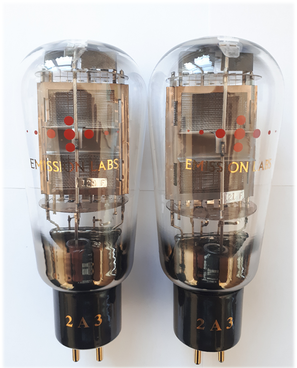
In June 2020 we celebrate 20 years Emission Labs!
for this occasion we are building a Special Edition 2A3 tube, the 2A3-Mesh-Globe. Globe tubes are for us more time consuming to build, because there is not this "shoulder" as with ST shaped tubes, which is used to attach and center the inner system. This again, at the same time however, is the virtue of such tubes! The mechanical contact of the inner system to the glass is very loose, so any mechanical coupling of the glass to the tube inside, is reduced. Yet most of all, they look very nice. Quantities produced, will not be very high. First tubes are expected in End of May 2020.
1.3.2020
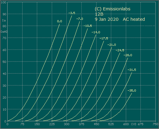
This is something really NEW. The 12B tube.
It sounds so simple and it is so true: A tube should be used in the application it is made for.
Yet many times, people try to do 'interesting' things, which may end up however in some disappointing aspects of circuit design. This may happen for instance when trying to use an output tube as pre-amplifier tube, a driver tube in a phono stage, or use a High Rp tube to drive am inter stage transformer. This is really a general issue, and has nothing to do with Emission Labs. More classical is perhaps the row of tubes, called ECC81, 82, 83 and 88, which each have their own intended use, and work best that way. Yet some designers are not interested in that, and do as they like, and end up with issues, which they call tube issues, instead of amplifier (design) issues.
In the list of possible applications, we have the high gain, high Rp tube, called 30B. Due to it's high Rp, this tube can not drive a a step up transformer any more. Which again is not needed, because gain is high anyway.
The 20B tube can drive a regular quality 1:1 inter stage. Or, 20B can even drive a 1:2 step up, provided it is of meticulous quality such as the Lundahl LL2746, which was developed specially for the EML20B. Even so, 20B can be used as a head phone output tube, in which application good sounds comes first, and Output Power as such is no real requirement, as long a it is enough.
The 12B tube, begins where the 20B tube ends, so to say. The gain of the 12B is actually 13x and not 12x as the name suggests, but 13B is the unlucky number, and not a good name for a product. So we choose 12B instead.
The lower gain of the 12B, has only one advantage: The lower gain. Some other parameters will change because of the lower gain, and this allows new applications. 12B can drive any reasonable quality inter stage. transformer, and any bandwidth limitations in the audio range should not occur. Moreover, the tube curves of 12B are also suited for speaker output applications. Though some companies have successfully developed Amplifier the 20B, this shows: Yes it is possible, but Output Transformer requirements are very high. You probably end up with a Lundahl or an ISO (Japan) transformer.
With 12B however it will be more convenient. Working voltage can be lower, and the output transformers do not have to be so strictly low capacitance as the previous mentioned. Though of course when using am ISO or a Lundahl, you will get the best performance out of those, with the 12B.
Note the many 'yes' with 12B
Application |
12B |
20B |
30B |
| Speaker Output | Yes | Possible | Difficult |
| Head Phone | Yes | Yes | Possible |
| 1:1 Inter stage | Yes | Yes | Difficult |
| 1:2 Inter stage | Yes | Difficult | No |
| Driver | Yes | Yes | Difficult |
| pre-amp | Yes | Yes | Yes |
Using Spice Parameters with 12B.
Spice is a simulation program, which gives a real simulation of all voltages and currents in a circuit, but the components used, need to be well defined. Like with tubes, the curves should be captured in some kind of a formula, which the program can use, to calculate it's results. Such special formulas, ideally are supplied by the manufacturer. We do so here at EML. But there is also freeware on the market, which can extract the formulas from existing tube curves. A very famous piece of freeware, PSU designer, from Duncan Amps, many know it. Though not visible when using it, PSU designer is based on Spice in a runtime environment. A run time environment, is a piece of software, which allows the end user to run a dedicated application of the (Spice) program, without having to install of even see Spice. However there is a freeware version of Spice available from Linear Technologies, which most people use. Please do not use this text here as a guide for how to use Spice. As this requires a lot of self-training, but when it works, you can simulate every tube circuit, and look with a simulated oscilloscope at all voltage and current shapes. It really works absolutely accurate, but as said, it can not be more accurate as the Spice models of the tubes you use.
1.9.2018
A (not so new) tube was born: AD1-Mesh-UX4
Well this is not so much a 'new' tube, it is only our AD1-Mesh tube, with a UX4 socket. This makes it possible to use this tube, where a UX4 socket is already there. Such as in the Lampizator products, or other with a UX4 socket.
1.9.2018
A new tube was born: 300B-2.5
The 300B-2.5V is a direct replacement for the 2A3 tube.
Users of 2A3 tubes have a limited choice of tubes to use. There was only 2A3 and 2A3-Mesh. With the 300B-2.5V we offer an alternative tube. The idea is to get a slightly different sound, and possible a small gain in output power for any 2A3 amplifier.
Dec 17th 2016
45B tube
It took a while, but here is finally something new!
We are working on a new 45 tube, called 45B, which can work at a higher operating point, yet it is downwards compatible to NOS 45 from RCA. This means, you can place it in a normal 45 circuit 'as is', and it will perform like any other 45. However when you are able to operate the amplifiers at somewhat higher voltage and just slightly higher current, it is possible to get more than twice the output power from the 45B, without having to change your output transformer impedance. This means in many cases you may not even have to change the output transformer, as most of the core's maximum flux is used to digest the DC current, and not so much for the (relatively) low output power. Roger Modjeski from the company RAMLABS USA, helped us with testing the recommended working points of the 45B. Thank you for this, Roger! Now we need to stock tubes for first orders, and product release is planned for March 2017.
Dec 12th 2011
About Cathode Tapped DHT tubes
Here is something really interesting. There has always been discussion about what is the best way to heat a Directly Heated Tube (DHT). The Control Grid Voltage is always relative to the cathode, but a DHT has two ends of the cathode. Which one to take? Or must we generate an artificial center perhaps? Furthermore, shall we heat the tube with AC or DC. Then those questions even mix in a practical situation. All together this is quite opinion related, and sure we don't want to lecture on that. Lets just summarize how things can be done, and then each user can build his own opinion.
Two point filament vs Cathode Tapped filament - Auto bias
Often seen methods:
- AC Heating with a Cathode Tap on the transformer. Seen with DHT rectifiers, but can cause capacitive path problems with amplifier tubes.
- AC heating with a virtual Cathode Tap, by means of two resistors. This creates a virtual cathode on the tube. Disadvantages are: A certain loss of output signal via the Cathode Tap resistors. The AC (music) signal present over those resistors is lost.
- AC heating of the filament, with one end to ground. Though often seen, this is definitely a wrong method. (See Left schematic, below). To begin with this can not work with auto bias. Any AC ripple on the power supply will be injected into the grid-to-cathode path. Not to speak about the capacitive AC current, being injected into the tube input signal. Besides, the tube curves are violated, meaning the real bias point is not the expected one from the tube curves. The last doesn't have to ne a problem, but it is a surprise often.
- DC heating, but connect it to a tube wired for AC heating. So just connect the DC where you normally would have connected the AC. Understanding the advantage of this is important, but hard to explain here in one line.
- RF heating. This is a nice option, since it eliminates any kind of mains frequency injected in the grid-to-cathode path. However the RF signal must be free of mains frequency, which can be present in the form of AM modulation, or a common mode signal.
It is obvious, that the above has always been a source of 'sound' discussions. Here is another version we want to add:
DHT Tubes with a real (Physical) Cathode Tap of the filament.
We have been producing the Cathode Tapped tubes for quite a while now. So the filament of those have a real physical Cathode Tap. It is a real metal connection in the tube base. Only we never had the idea to connect it to the outside world. Reason for having the Cathode Tap still, at production the tube is forced to be mechanically as symmetrical as we can do. The result is a drastically reduction in tube hum, ever since we build those.
The idea is now, to connect this Cathode Tap to the outside world. This means we need five connection instead of four, and the UX4 base can not be used any more. We need to use an octal base for such tubes. This Cathode Tap opens a world of possibilities.
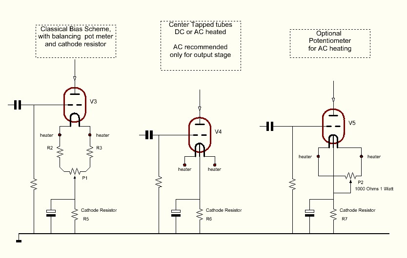
Two point filament vs Cathode Tapped filament - Adjustable bias
From the above left schematic 1, it can be seen there a common path for the Music signal, and the heater current. Needless to say this is source of problems.
The middle schematic has so much simplicity, it may seem familiar to you. Though this is a new method. The advantages are:
1) Anode Current is easy to measure (This is impossible with the left schematic)
2) Signal Path and heater Path separated
3) Heater is balanced, so hum is
not added to signal.
The schematic from the right, shows how to add a hum potentiometer, in case you heat with AC and you don't want to do without a hum potentiometer.
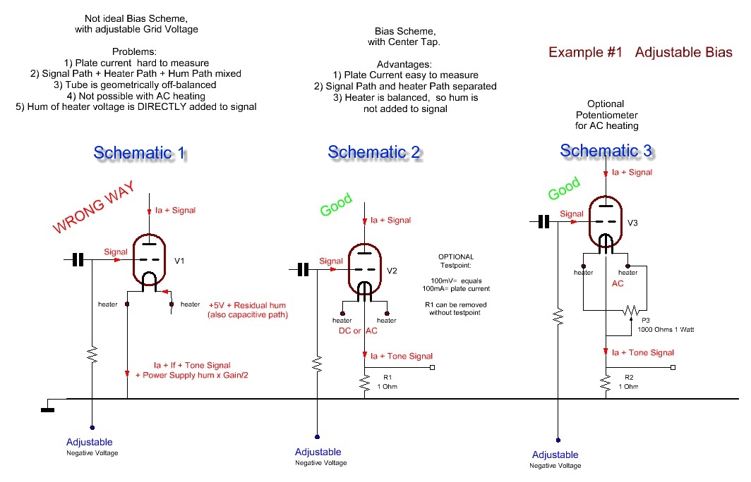
BLACK BOX APPROACH
Directly Heated Tubes (DHT) have good rejection of the AC heater signal, but this ratio is not endlessly high. For this reason, the left schematic (above) is a bad one to use, though it is in fact the most common one. What a shame! Let's just look at a tube as a black box, to explain better what I mean by rejection of the AC heater signal. The black box theory doesn't look at the schematic, or what is inside the black box. It just describes the black box an object with terminals, and each can be an input or an output as well.
.
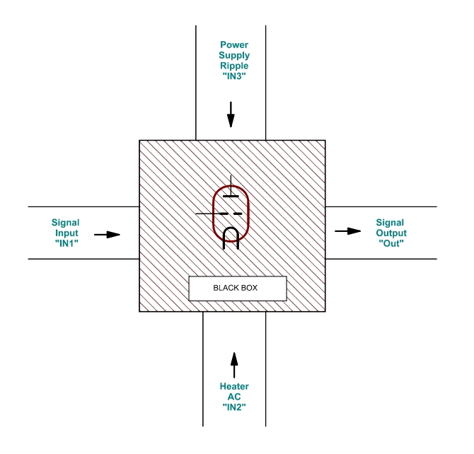
In this example we regard the heater as input terminals, and we do so with a 300B tube. So the input signal to the black box is 5 Volt AC, and we want to see if something comes out at the Anode. The result I cam already say, it is 0.5 to 4mV or more, depending on the tube quality. Whereas 0.5mV is for a high quality, nicely burned in, new tube, and 2mV is rather for a Russian 300B, and 4mV for a tube with a defect, such as end of lifetime. Output hum can not be zero, as that would only apply for an infinite good tube, and such tubes would need to have curves which are straight lines. However they are what the word says: Curves. In a practical situation, let's just make the calculations here with 1mV hum. . Given a SE output transformer of 3500k primary and 8 Ohms secondary, this would mean a transformer windings ratio of 21. (Square root of 3500/8=21). This factor 21 means we have 21mV AC on the anode, as a result if 5Volt AC on the heater. So now we can begin to capture this in numbers. The attenuation factor is 5/0.021=238. We do have to say, this applies for schematic #2 and #3, and NOT for schematic #1. .
Conclusion: This number 238 is a characteristic of a new, good quality 300B tube, and you can use it for calculations. |
Consideration of above schematic 1
This is an usual situation, we need to look better into it. Always, the input signal of the tube is the difference between the grid and the heater. On the left end (the grounded end) of the heater, can be no signal because it is grounded. On the right end of the heater is +5V DC, and some AC hum of the power supply. Even a good stabilizer IC is in the range of millivolts. We just take 2mV here, for the calculations. Perhaps some IC's are better or worse, but in practical situations you have also the wiring, and the hum problems caused by that, and 2mV can sure happen. This small AC signal, on the right end of the heater will give some small hum on the output, which we can calculate. On the right end of the heater, it will appear fully as input signal, relative to the grid. On the grounded end of the heater, no signal can result. So the average is simply 50%. Meaning 50% of the AC hum will go into the tube as input signal.
The formula for this is: Out = IN1 * Gain + IN2 * Gain/2. (see the black box picture for the reference of 'IN1' etc).
The gain of a 300B = 4x
So: Out = IN1 * 4 + IN2 * 2
Without music signal, IN1 =0, but IN2 is still 2mV (from the stabilizer IC). The output signal on the anode will be IN1 * 2 = 2 * 2 = 4mV. With the transformer windings ratio of 21, this will translate into 0.2mV at the output. This is of course a much lower number as Schematic #2 which had 1mV with AC heating. So you might say, schematic 1 is better than schematic 2. However it is not! Remember, schematic 2 has AC heating in the considerations so far.
Consideration of above schematic 2
Now let's see what happens here, with the DC heating voltage from the same stabilizer IC, which has 2mV of hum on it. We take our number 238 and with that we can say, 3mV of hum on the heater will give a stunning low 8µV on the anode, and only 0.4µV on the 8 Ohms output.
Results
Schematic #1 DC heated: 0.2mV at the speaker.
Schematic #2 AC heated:
1mV at the speaker.
Schematic #2 DC heated: 0.4µV at the speaker.
Note: Only heater to Output signal transfer was considered, but there is also a signal transfer from power supply ripple, to the output. (see the black box, 'IN3' to 'Out'))
Conclusions:
- Schematic #1 DC heated, is barely a good schematic. 0.2mV is inaudible with normal speakers, but is may become an issue with high efficiency speakers, or headphones.
- Schematic #1 DC heated will fail if used as a driver circuit for another tube. We are missing here, the transformer windings reduction (21 in this example) so we are going to see 4mV of hum at the output of such a driver tube.
How to design?
Whatever you do, schematic #1 is non-preference since it has no ripple rejection ratio, but even 3dB GAIN. Such a schematic will only work with extremely quiet DC power supply, of the kind that many will find difficult to build. It is better is use schematic #2, since it's ripple rejection ratio is so high, you can do without electronic regulation. Simply a passive stabilized circuit will do the job. Like a plain C-R-C circuit is FINE already, and will outperform circuit #1 using an integrated circuit. So the difference between schematic 1 and 2 is 25dB less heater hum.
Where does the Cathode Tap come in?
You may object, schematic #2 can be achieved also with two centering resistors. This is true, but not quite. If you want really good centering, you will need very low values of those resistors, and they use considerably energy. This makes the power supply capacitors larger, the transformer also, and you have larger charge peaks for the capacitors, which will radiate into other parts of the amplifier. So the resistors are chosen often at a much higher value, to make things more practical. Then, in the end they become a bad compromise, and you loose the good rejection ratio you had in mind. Note, when they get too high, you also start to loose anode signal via the resistors, as the anode signal must pass through them. So the amplifier gets less efficient. In a practical situation we talk about 0.3 Watt loss in a 300B Single Ended stage. Also the artificial center is connected via a resistive path, all of this is not a clean and nice way.
The Cathode Tapped tubes do a much better job here. They are not a compromise, they give a real true Cathode Tap, directly on the cathode itself, and yet it consumes no heater power.
You are encouraged to discuss it on the EML forum
June 5th 2011
5U4G and 274B now with ceramic base.
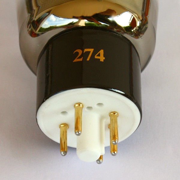
Click image for a detailed picture
Feb 21st 2011
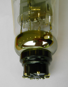
Gold Grid Wire
This is not something very new. However there were questions if we use gold grid wire at EML, and it a nice topic for the lab report. Well yes we do ever since many years now. The advantages of this are several, but also this requires tighter control in production, since gold is an emission killer. So clean working gets more important then ever. The result is more stabile bias, and an increase of the abuse proof level. So in case you do make a mistake, the tube is more forgiving.

Click the image for a detailed picture
If you ever checked the bias of EML tubes, you will know they get stabile amazingly quickly. When you have a Anode current meter, you can see more things from the way the tube heats up. Let's take the 45 tube as an example. It is biased at 32mA in most amplifiers. With much used historical tubes, they may initially reach 24mA, then 25, 26, and after loong warm up come closer and closer to the normal value. Nothing against such a tube, but it does indicate quite a lot of use. With the EML45 mesh, you switch the amplifier on, and once the tube starts to draw current, you see the meter needle go up fast, then it reach it's required value without delay, and then stay there like fixed. No drift, no changes. That is quality. There are more secrets inside the tube to make this happen, but the gold grid is one of them. Staying with Anode current of the 45 tube (normally 32mA), an observation with Chinese tubes is you may not always the same Anode current. Also on a tube tester, particularly the Hickoks, you do not always get the same reading. Perhaps that sounds familiar to you, and you don't know what causes it. Well we do, but that's too much here to explain. With EML you have the same value always. Observe this carefully with other tubes, NOS, used, Chinese, and you'll notice that.
.
Jan 1st 2010
45 Globe anniversary series
Perhaps some of you remember back in 2003 we had a limited production of the 45 Globe. It was a special project based on the initiative of some of our US customers, who also helped us with the logistics(Thanks Ed S.) The 45 tube is one of the few original historical tubes that can be found in the old globe versions. Unfortunately though, with the historical 45 Globe tubes, these are always used, and strong ones are just very rare. So, logically there have always been requests to re-build the globe version. However, this is difficult to do since there is no mechanical contact of the internal construction with the glass. For us, this means while closing the glass, the Anode is not always in the desired position inside the glass envelope, and it raises production costs. Additionally, more emphasis is placed on the final packing requirements for transporting the tubes. So these are the circumstances for producing 'real' globe tubes that have a 'true' floating system inside. It does not apply to these globe tubes that some manufacturers make which have the internal system still attached to the glass.
In celebration of our tenth anniversary, we have produced a limited stock of the historical 45 Globes, the ones with a floating system inside. They are truly special. When they are sold out, we will not produce them so quickly again.
Click here for some more information on this project

OUR BIRTHDAY!
October 2009
Time flies!
In 2010 it's going to be ten years ago that we started to build our own tubes. To remember this, we will offer a limited version of some tubes that we were asked to build before. The official announcement of that will be at December 15th. Subscribe the mailing list here to be informed about it automatically.
Feb. 2009
New rectifier
We're getting more and more request for a tube like Telefunken RGN4004. This tube is so rare, that we couldn't even find a graphical data sheet. Only data in numerical form. Well anyway from this we know what the tube does. For making a stereo amplifier with the 1605, the 5U4G is too small. Another reason to think about a larger type rectifier..
Dec 17th. 2008
A New tube is born: EML1605
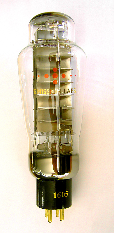
We've said it before: There is nothing new in tube technology since the invention of the magnetron tube in the 1940's. So what do we intend to achieve with the EML1605? For answering that question, first look at the resemblance with the part number 1610, which is a beautiful made tube, constructed by our competition, many years ago. When looking into the 1610 bulb, you see two triodes wired in parallel, mounted on top of each other in one glass bottle. A well known historical example for paralleled audio triodes is the dual Anode 2A3, as the Chinese still build it today. Since designing is the art of making the right trade offs, there is always pro and contra in what you decide. AT EML we have been looking at the possibilities to make a larger tube that the EML520B. The reason why we did not parallel two triodes, is described below, also we were simply able to build a tube with a higher Anode power by using the best of our technology. The Anodes of the 1605 are longer than with the 520B, and also have higher Anode distance than normal (more bout this later). Some other things that we can not explain here, helped us to further increase the power. We did not get as much power as the KR 1610 though, and for that reason we gave our tube the part number EML1605.
What exactly is the 1605?
This is not 'another' 300B on steroids. The 1605 is made to fit in most amplifiers that can run on the 520B, though you need to be careful with that, and you can not just Plug & Play it. With the 1605 we have been aiming to get the right sound in the first place. People who investigate the sound of triodes, observe that the larger the triode is, the more dominant it sounds. When going in the other direction, it can be observed that the smaller kind of Triodes like the 45 and AD1 sound more sweet, more silky than a 300B. This sweet and silky sound is regarded the purest triode sound by many. This sound character is caused by the higher output impedance of such tubes, combined with higher gain. It is the reason why tubes like PX25 and 211 (VT4C) still have this silky sound, and still can do so at very high power too. PX25 and 211 are tubes with significantly higher gain (and higher output impedance) than a 300B. So for us it was clear that if we would make a tube with higher power, the way to avoid the dominant sound is by increasing the gain and the output impedance. One of the things we did for that, was increasing the Anode distance. (See Note1). Since higher output impedance is always difficult for the SE transformer, we were more generous with gain increase than with output impedance increase. So as you see, designing is the art of making the right trade offs, and these were the ones we made. The higher Anode distance of this tube brings that you need to operate it like 50 or 100 Volts higher that a normal 300B, so it makes the power supply a bit more complicated. However this 'complication' is not so large, and you get rewarded with the higher gain of this tube, making the driver stages more simple, and making the driver tube working at less distortion. So for now, we will leave the final word about the 1605 to the end-users.
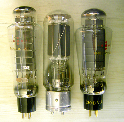
From left to right: 1605, 211, 520B
Note1). For the real engineers...more Anode distance results in higher gain, and less feedback INSIDE the tube. That resembles the 'Hr' (H-Reverse) parameter from the transistor black box theory. Looking inside a PX 25 or 211, you will see the Anode distance is twice as much as with 300B. The electrical field of the Anode is in 180° Phase shift with the grid field, and these fields add up by definition. So a larger Anode distance gives a higher Anode field gradient, thus working less against the grid field, and increasing the gain of the tube.
.
Oct. 4th. 2007
A new tube is born: AD1-Mesh
Link to Emission Labs ®data sheet. Together with Yamamoto Soundcraft Japan, we have been working on the AD1-Mesh. Final introduction is planned for December 2007. Whatever the reason, don't ask us, but it seems pretty sure that DHT tubes in 4Volt technology produce finest sound. All very expensive and highly sought after NOS tubes are always the 4Volt types. Like: PX25 and PX4, but also RE604 and RES 241.
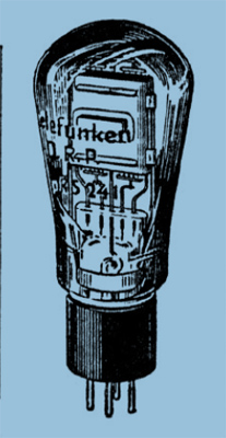
Even the small RE134 is expensive now. Add to this the AD1 which is something like a 2A3 in 4Volt technique. Note the AD1 has lower filament power, and slightly different tube parameters, but it can be used in any 2A3 design without changes to the electrical diagram, other than the filament voltage which is 4V with the AD1. Let me quote Rainer zur Linde, who wrote several books in German language about building HiFi amplifiers with historical tubes. He writes: 'AD1 is the queen of European DHT triodes, also marks the end of the period of DHT tubes'. I think there is no better way to describe this tube.
Intended for larger size radios and cinema amplifiers, AD1 was introduced just before the second world war. After the war, the upcoming industrialization ended the production of AD1, before it had really started. It is not known how many AD1 were made, but some estimations say only 50.000 pcs. Some words about the special P8 socket: The AD1 socket type (P8) got obsolete, because it can only be connected to 'wired' tubes, and not to tubes with the pins that go through the glass. (So the wired tubes are the ones that have their connection wires coming through the glass. The 'pins' type for instance like ECC81). The P8 socket as used for the AD1 is amongst the best ever made, but as we know it was unfortunately too large size, and not industrial. A nice feature is, they pull the tube inside the socket, and then the tube base closes the socket like a lid, so no dust can get in. This is really High-Ended! You need no tube retainers, and these sockets are inside always clean. Also you don't need to press the tube in the socket. When you put it in for 80%, the socket pulls in the tube by itself. What is also EXCELLENT is, you can access the contacts for cleaning very simply from the outside. Oh, and by the way this socket can NEVER wear out. For those of you who ever had nasty problems with scratching Octal or Noval sockets, you know what this means. You have to clean it with spray, you can not really access the contacts, and after a while the problems can come back. With P8 sockets that will never happen to you.The electrical data of the Emission Labs ®AD1-mesh tube is almost identical to the original AD1, as made by Telefunken. The difference will be described here. All properties like Anode impedance, transconductance and tube bias are fully identical to the historical tubes. We like to mention here, that the historical tubes had a method to apply the cathode layer, which was not the finest, as with modern tubes. By the historical method, the filament coating was applied by evaporating a depot of Barium inside the tube Anodes. When looking at earliest AD1, such as Telefunken, you will see a bubble in the middle, which was the depot container. It is empty for an activates tube of course. This method gives a very thin layer of emissive coating only. The result is, historical tubes could be made with very low filament current. This was important at those days, because radios operated from batteries. For the rest, there are some disadvantages of this historical method, which is risk on lower lifetime, and grid current. For sure the historical tubes are extremely sensitivity for accidental abuse. If you overheated those, you will immediately destroy the tube, and you will have grid current, and/or loss of emission. However it was possible to build first class tubes this way, but we think only Telefunken had this process fully under control. They used poisonous chemicals which are forbidden now. Also the environmental conditions in a tube factory were dangerous this way.The Tungsram and Philips suffered from the mentioned problems, mainly loss of emission after little use, grid current, and bad vacuum. Later types from Valvo appeared with very large bulbs like 300B, and very large Anodes. These are good quality also. Production of modern tubes, is done with classical Barium Oxide coating, which requires more filament current, but enables tubes with more lifetime, and also some accidental abuse will not damage the tube immediately because the Barium depot in the filaments is larger. So in short, the difference with EML AD1-mesh is, that it uses more filament current than the historical tubes, and for this the tube rewards you with longer lifetime and higher reliability. We plan to make this tube with 4Volts. 1.5 Amps.
Oct. 4th. 2007
A New tube is coming: 1605
Just a short note here, the official announcement will come in Dec 2007. We have finalized the 1605 tube, which is going to be the next larger tube after the 520B.
Oct. 4th. 2007
A New tube is coming: 300B Mesh
Here is something nice we want to report about. It is the new 300B-Mesh, and we have it ready for shipment by Mid December 2007. This tube is a real woven wire mesh tube. Please take good note that Emission Labs ®is the only company building mesh tubes that are indeed Mesh tubes. The Chinese companies produce lies about this! They offer fake mesh tubes, that are no mesh tubes at all. When you look at them under the microscope, you quickly discover the fraud. You will see they use simply Solid Plate tubes with tiny holes punched into it, and tell to you these are mesh tubes. These fake Chinese mesh tubes provide you only the nice optics of a mesh tube, but again they not mesh tubes at all. The EML 300B Mesh is a long Anode version, it's Anodes are 25% longer than normal 300B. Like this we could increase the Anode dissipation up to a point which is useful for SE amplifiers. So the EML 300B Mesh has 28 Watt continuous dissipation, and has a peak power of 35...40 Watt. Since a true high end 300B design runs the tube at 22...28 Watt anyway, and not at 36 Watt, the EML300B Mesh sure has it's applications. It is only at this level, that any 300B tube develops the sweet sound characterized by this operating point. Consequently at this operating point the 300B Mesh will add the maximum of what it has to offer.
On the other hand, when you have a 300B amplifier on steroids, like the kind that proudly gets 'so an so many' Watts out of a normal 300B, then the poor tube is likely to be biased at 35...38 Watt. Still there is the never changing rule with tube amplifier design, that highest output power, and finest sound do not combine well. So with a 'muscle' amplifier, the sound quality is not optimized, but the output power is. For this, the 300B Mesh is not intended. This kind of amplifier will benefit most from a tube like 300B-XLS, because the 300B-XLS doesn't have to work very hard at a Anode dissipation of 35...38Watt. (since 50Watt is even a piece of cake for the 300B-XLS). This brings the design back to basics, where it says that a tube sounds best when biased slightly above medium Anode dissipation, and not close to maximum Anode dissipation.
Oct. 4th. 2007
2A3-mesh
Our 2A3-mesh has went through some changes, which are s more like evolution. Just please don't think we change all kind of things all of the time. This tube has been very reliable ever since we made it. In the newer versions, with the gray mesh wire, we build-in this part of the philosophy that a tube sounds at it's best when it doesn't have to work very hard at the actual operating point. Now, with a tube like 300B the operating points we see on the market are extremely variable. Some take the highest possible dissipation, even risk short lifetime of the tubes with this, and an amplifier like this can have a bit dominant kind of sound. Mainly the Japanese prefer the silky, sweet sound that results from the more classical operating point at 60...70mA and 22..28 Watt Anode dissipation. However, when we talk about the 2A3, all designers speak one language. It is so amazing, every Auto Bias SE 2A3 amplifier runs at Vb=295V, 60mA. However this is also the MAXIMUM dissipation for the 2A3. But please consider, no tube will be reliable at it's maximum dissipation. So our solution is, we had to increase the maximum dissipation if the 2A3 mesh, somewhere above 15 Watt, and that's what we did. In case you are interested in the numbers, here is where to look. The new, gray wire mesh 2A3 can even do more dissipation as it writes there, but seriously do not ask. The idea is to use the maximum as in the data sheet, and then we know the tube is used 100% safe, and under normal use conditions this new version should last longer than people may have ever though was possible. How much longer, we just can't say ourself at this moment, that will simply take many years before we know.
Dec 10th. 2004
HIGH GAIN TUBES
Many customers have asked us to build higher gain tubes. We are working on a series of those tubes. In the pipeline is a direct replacement for the obsolete AVVT 20B. As a spin off from this project, we plan to make a family of those tubes! The idea is to make: EML 20A 20x gain tube for pre amp or driver applications
EML 20B 20x gain tube for driver or output applications
EML 30A or 30B 30x gain tube for pre amp or driver applications In semiconductor technologies there is always the 'first silicon'. Well.... here is our 'first metal' . Some other prototype pictures will be placed later. These tubes will make it possible to build an 'all EML' amplifier. With the 20B you can replace the complete driver + pre amp, using ONLY this tube. For a 300B you need 60Volt AC on the grid. So you need an amplification of 60x. With the Lundahl transformers it is possible to use a 4x step up transformer and the total output signal will be 60..80Volt coming out of the transformer. Another option is to use a 4x input step up transformer. This is even better, because now you replace the (noisy + humming....) input tube by a transformer! So from 1 Volt AC input, you make 4Volt signal with the transformer. This is amplified by the 20A, and gives around 70Volt, resistor loaded, or 75Volt choke loaded. The 300B needs only 60Volt, so you will have below 1Volt input sensitivity! The complete amplifier can now be made from one 20B and one 300B tube. For resistor loaded, the 20B may be better, because it can do higher power. The choke loaded stage can be made with the 20A at somewhat lower power, since a choke loaded tube is running almost unloaded for the AC output signal. The input transformer will also give you perfect input isolation, and cancel any hum coming from the input cables. This is why the Japanese LOVE input transformers so much. (And not only the Japanese) . For the real freaks... It is possible to build a COMPLETE amplifier ONLY from the new 30A. This tube has enough output power to give a few Watt. For full output signal it needs something like 7Volt on the grid. This can be done with an input transformer, with for instance a step up factor of 5x. The result is 1,4 Volt input sensitivity! Most CP players and pre amps can give this voltage. With the 20B something similar can be done, and this tube will give more output power than a 2A3 tube even! So the whole 20B amp will have only one tube!!! 
enlarge These tubes will all have 'large box' anodes. This is a nice technology. It makes not only that the tubes look nice, and have a much brighter glow effect. It also improves the high voltage capability of these tubes.
21-Aug-2003
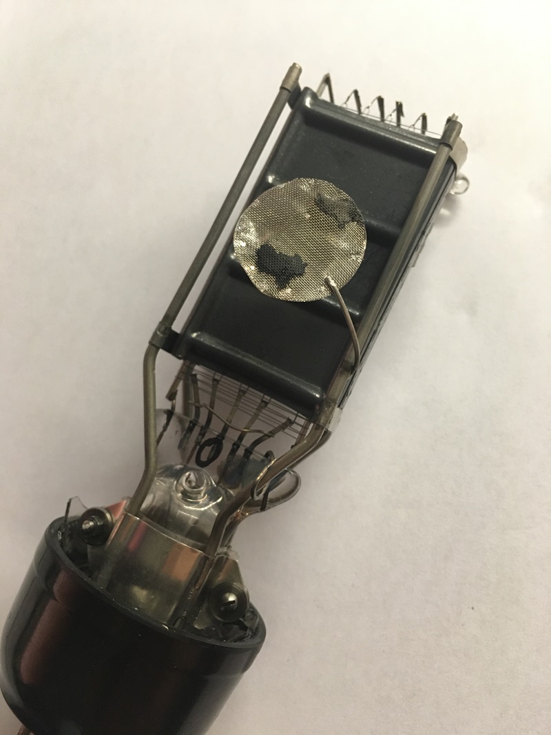
Top Getter. (what is this?)
One of the real secrets of tube making is tube activation. This is a complex process that needs to be done to make a new build tube come alive. Modern tubes will not 'just work' by vacuum pumping. The tube is heated inside an microwave generator, and while the filament is treated electrically in a special way, slowly the gas pressure will fall, and the tube comes alive. When the filament is switched on for the first time, a cloud of dirt (in gas form) will come out of it, and the gas pressure in the tube will rise while doing this. Simultaneously, the filament emissive coating starts to build. At this critical moment the gas is attacking the new born filament, and tries to poison it. This is unwanted, but unavoidable. While doing so, the vacuum pumps run at full power, eliminating the gas quickly. The person who does the activation process, is now doing something with great influence on the tube lifetime. There are many quick ways to do this less good. The right way is very time consuming and requires monitoring of the gas pressure all of the time. (Here you see one difference between hand made tubes and machine made tubes) Now, once the filaments stops producing gas, the bulb pressure will fall quickly to it's final value and while this happens, the filament develops it's initial function, meaning only it works in some way, and the tube can now be electrically heated. The better the operator has control of his process, the longer the tube will live, and his patience is the keys to good result. After this step, the final activation can be started, at the end of which the getter will be flashed, to create a vacuum which is so good, it can not be measured with normal instruments any more. When the getter is flashed, this is the final step of activation. During a few seconds the getter material will be evaporated from the getter ring, and from there condense on the glass. During this moment, when the getter metals travel to vacuum, it catches all gasses on it's way. After this, the getter metal is now on the glass, and is much less active now. Cleaning function is very low, and is increased at higher temperature. There are some pro's and con's for every position of the getter flash, like at the bottom, at the side, or at the top. Also optical reasons come in of course. A nice place would be at the back of the tube, opposite to the Anode, but nobody wants that, you can only like inside from one direction.
|
|
| Top getter Bottom getter |
.
2-July 2002
520B-V3 vs. 52B
The 52B was a power tube, original designed by Alesa Vaic and Riccardo Kron during their years of cooperation. At EML, a replacement part for this tube was offered under the same 52B part number. The EML 520B-V2 or V3 are much improved versions, giving virtually everything the amplifier designer will love. When designing tubes, most parameters are in competition to each other
So when you change the Anode distance to get more amplification, you will be punished with higher Anode impedance. If you then reduce the Anode impedance by choosing a larger grid spacing, you'll loose amplification, and now the tube even needs a higher Anode voltage than before... Whatever you do, it will create something good and something bad, and always you will find that a good tube is hard to improve. With a good tube, the result is a set of parameters, that amplifier designer will find pleasant to use. This tube makes it possible for him to build the amplifier, and make it work the way he wants it. Now let's look at the V3 (and V2). Those tubes really have something special. We made improved ALL (but one) parameters in the positive direction. The only parameter that changed in the negative direction is filament voltage / and or current. Remember, one trade off you always must make. We think more filament voltage or current is no big problem today, and now let's see what the engineer gets in return for it. It's a LOT!!
Overview:
| 52B 520B-V2 | Change |
| Filament voltage6 Volt6.5 Volt | + 8% :( |
| Filament current2.3 Amp2 Amp | -15% |
| Typical dissipation55Watt69Watt | +25% |
| Anode impedance595Ohms470Ohms | -21% :) :) :) |
| Transconductance (also called Gm)6.5mA/Volt8.5mA/Volt |
+31% |
| Gain4.04.0 | The same! |
| Peak Output23Watt27 Watt | + 17% |
520B-V3 Changes only listed for the filament.
| 52B 520B-V3 | Change |
| Filament voltage6 Volt5 Volt | -17% |
| Filament current2.3 Amp2.7 Amp | +17% :( |
So... with this tube we have a real winner! It is intended for new designs, but in many cases, the 520B-V2 can even directly replace the old 52B. AVVT specified their 52B at: 5.0 .... 6.3 Volts. Just ask what tube to take, we can often supply selected versions to you, that work at also at lower voltages. So the process is like this: Do you want to replace our old AVVT or KR 52B by the new 520B-V2 or V3?
- Q1: What's the filament voltage of your amplifier?
- Q2: Does it have electronic regulated bias? (Like for instance Wavelength Audio uses?)
- Q3: does it have the possibility to adjust the bias?
Please get those answers first, and we can quickly answer you.
MAY 2001 - Mesh Window... (what is this?)
MESH 45..... The technology is not new, but it was off the market, from 1940 until the year 1999. In that year, I worked with AVVT, and with that company we introduced the AVVT 2A3-Mesh, the first mesh tube made since 59 years. It is beyond this post, to explain all of this, but here you can find more about it. AVVT is now history, and at EML we picked up this idea, but we took out the main problem these AVVT mesh tubes had: You can hardly ship them. Instead of that, we use a mesh window.
At the moment we just briefly want to announce our mesh technology, using a mesh window. Mesh is a virtually resonance-free material. In the industry, special mesh cables are used as dampers. (We will show you some pictures of these interesting devices later) Unfortunately, when making mesh Anodes, the nickel mesh is very soft, and can deform easily. We have found a simple and effective way to combine the stability of the Solid Plates with the sweetest sound of the wire mesh tubes. We plan to call this the tube '45-Mesh', and it should be available in May 2002.