Saving the world from Solid State
Technical Bulletin: TB-06
PX4 CONFUSION RESOLVED
Written by: Jac van de walle
The ancient test method.
PX4 was developed in the 1920's by the MO Valve company England, and marketed under the OSRAM and MARCONI brands, beginning in 1928. At OSRAM, as they made the PX4 data sheet, there were not many good tube testers around. The "AVO Valve Tester", was the best, and it still is a very desirable and useful antique tube tester. OSRAM added in the PX4 data sheet the special settings for this tester. Which made a lot of sense, because everybody in England was using it, and this method is excellent.
How the AVO Valve Tester works
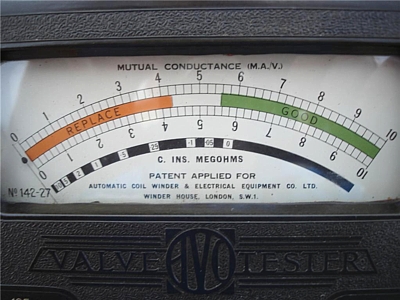 This tester checks if the tube is still good at the "diode curve" which is a curve like all the others, just this one is at zero volt grid voltage. Now you can bet when a tube has lost emission, and tests weak at -10V Grid, it tests weak on all curves, including the 0V Grid curve as well.
Using 0V, has the advantage, that the grid voltage plays no role. This was done for a very good reason. Any tolerance in plate current of a factory new tube, is not caused by tolerance in emission, but caused by tolerance in grid voltage. When using a negative grid voltage, despite of having 100% emission, any random tube will show a different plate current. This gives room for the useual false explanations, this is caused by difference in emission. If the plate current is lower than 100%, they say the tube is less good. But when tube has 120% plate current, what will you say? Does it have 120% Emission? That would be foolish to say, because it's like filling a bottle with 120%. The same tube supposedly having 120%, will show 100%, if tested at Ug=0V. As you will agree, a tube can not have 100% and 120% emission at the same time. So this method with Ug=0V is indeed the better one. Another advantage which we achieve by this is, we bypass this problem that transconduction depends heavily on the plate current. At a fixed negative grid voltage, a random plate current will occur (+/-30%), due to grid voltage tolerance. Then, measuring transconductance this way, would give the wrong result almost always, because transconductance can only be measured at the plate current which belongs to it.
In a nutshell, this is the reason why testing at zero volt grid voltage is a very good idea, but it only makes sense if you have the test data for it. Still at zero volt, the transconductance can be measured, by going to -1V grid. But here comes the thing. This transconductance at zero volt grid, is ANOTHER as the grid voltage for intended l use. Rarely, curves are published for a tube with transconductance vs. plate current. But this curve exists for every tube.
So a tube data sheet, ideally lets you know the transconductance at a few working points for intended use, AND gives you for testing, the transconductance at grid = 0V. Unfortunately, this excellent method got lost. But at the year 1928 it was just what OSRAM did, and this was a very good thing.
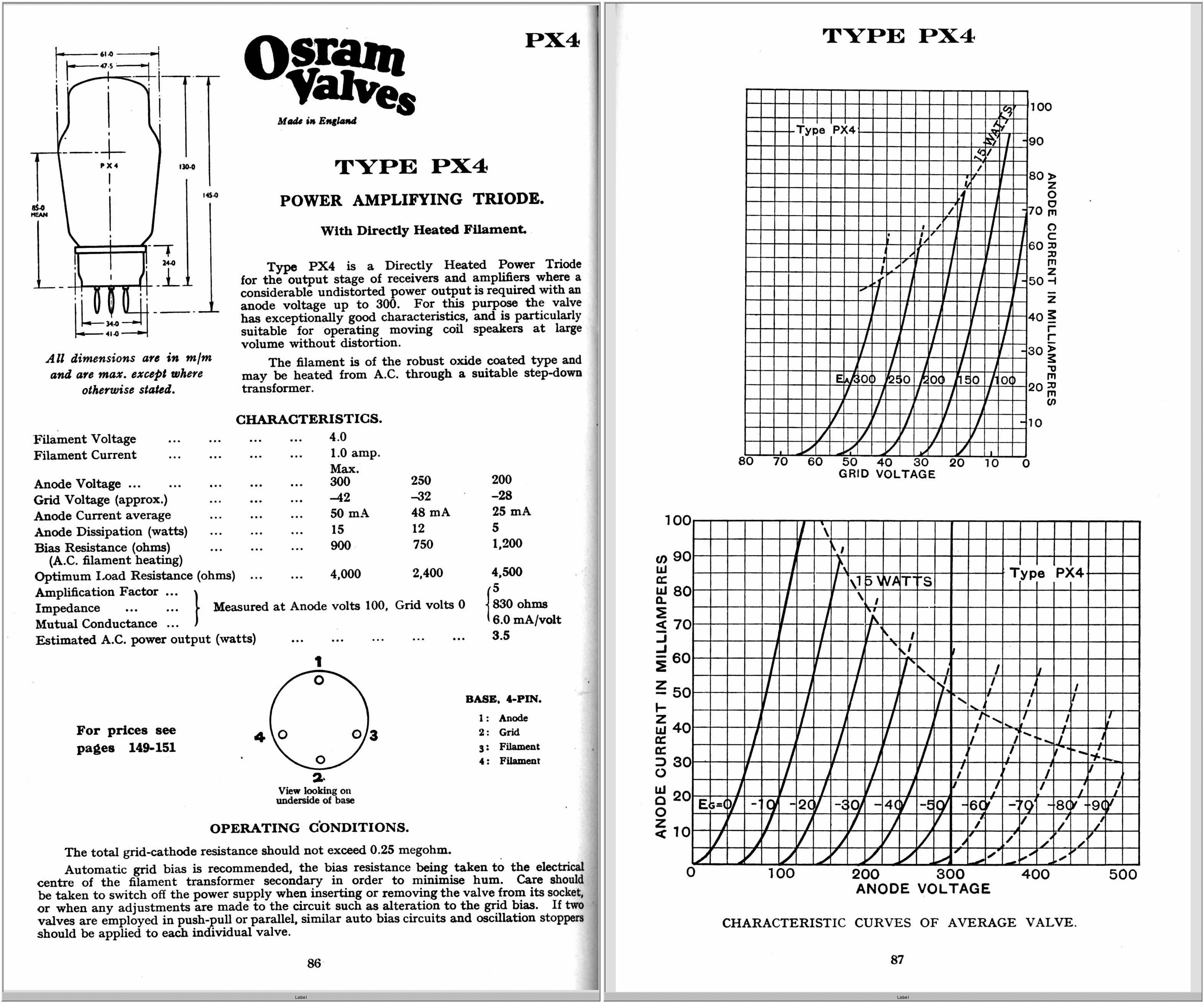
Now comes something important. Do not ask me why, but with the PX4, they have not given transconductance for the NORMAL intended working points. There are empty spaces here in the data sheet. Instead of that, there were good tube curves, from which anyone can derive those numbers as needed. This is not necessarily wrong, but a problem arises when somebody does not read the data sheet very well, then sees a transconductance number, and just that takes that as the transconductance. Often fully unaware, there is no such thing as 'THE' transconductance, but this number depends with a factor 1:2 on the actual plate current. The difference is that huge with all tubes, and PX4 is no exception. So when buying historic PX4 tubes on Ebay, you can only test them, using the data OSRAM gives. which is 100V plate, 0V grid, and then you should get 65mA and 6mA/V transconductance.
These is all that was published by Osram: (click here for a link to the original data sheet)
Original Osram Specifications | ||||
| Anode Voltage | 300V
(Max) |
250V |
200V |
100V |
| Control Grid Voltage | -42V |
-32V |
-28V |
0V |
| Anode Current | 50mA |
48mA |
25mA |
65mA |
| Anode Dissipation | 15Watt |
12Watt |
5Watt |
6.5Watt |
| Bias Resistor (AC heated) | 900 |
740Ohms |
1200 Ohms |
|
| Load Resistor (Ra) | 4000 Ohms |
2400 Ohms |
4500 Ohms |
|
| Gain (Mu) | Left Blank by Osram
|
Left Blank by Osram
|
Left Blank by Osram
|
5 |
| Transconductance (Gm) | Left Blank by Osram |
Left Blank by Osram |
Left Blank by Osram |
6 mA/V |
| Anode Impedance (Rp) | Left Blank by Osram
|
Left Blank by Osram
|
Left Blank by Osram
|
830 Ohms |
| Estimated power Output | Left Blank by Osram |
Left Blank by Osram |
3.5 Watt |
|
This situation with the blank spaces was fully misunderstood as some companies began to make replicas. They filled in the empty spaces with Gain=5 and trans conduct ace =6mA/V. Which is dead wrong. Even worse, they tried to make the tubes work that way, which is technically impossible, and such a tube will never have the identical curves as the original PX4.
At Emission Labs , when building first prototypes of the PX4, we ran into this trap as well. We just couldn't get the specifications right. When the working point was right, Gm was wrong. When we Gm was right, the working point was wrong. It just didn't seem to make no sense to us, and frankly it delayed the development of the EML PX4.
This historical error, and how (we think...) it happened to the Chinese tubes is actually quite interesting. We resolved it, 90 years after the first publication. This is why I wrote this bulletin, just to point this out better. Now, we sometimes get asked, how come that other companies that build replicas, use indeed the historical tube curves, as well as those WRONG data sheet values? Which should not be possible. Well, do not ask us, better ask them, and enjoy the reply :)
Missing OSRAM data reconstructed from the 1928 curves
Original Osram Specifications in black
| ||||
| Anode Voltage | 300V (Max) |
250V |
200V |
100V |
| Control Grid Voltage | -42V |
-32V |
-28V |
0V |
| Anode Current | 50mA |
48mA |
25mA |
65mA |
| Anode Dissipation | 15Watt |
12Watt |
5Watt |
6.5Watt |
| Bias Resistor (AC heated) | 900Ohms |
740Ohms |
1200 Ohms |
|
| Load Resistor (Ra) | 4000 Ohms |
2400 Ohms |
4500 Ohms |
|
| Gain (Mu) | 4.9
|
5.6 |
4.6 |
5 |
| Transconductance (Gm) | 4mA/V |
5mA/V |
3.2mA/V |
6 mA/V |
| Anode Impedance (Rp) | 1233 Ohms |
1133 Ohms |
1448 Ohms |
830 Ohms |
| Estimated power Output | 3.5 Watt |
|||
The heater current of PX4
At first there was a low power version, with a 0.6 Ampere heater. Later the high power version with a 1.0 Ampere heater was introduced. This already indicates a lot. So 0.6 Amp was tried, and you might find some PX4 like that, but 1.0 Ampere as used later, was a better idea.
The EML tube has to fulfill also these requirements:
- Significant longer lifetime as the historical tubes or Chinese tubes, as we want to apply the 5 years guarantee program on PX4 as well.
- The tubes can withstand accidental abuse (to some limits of course) much better than any other tube.
At EML, we say 1.6 Ampere is a much better idea. PX4 was developed in England.
How the confusion continued
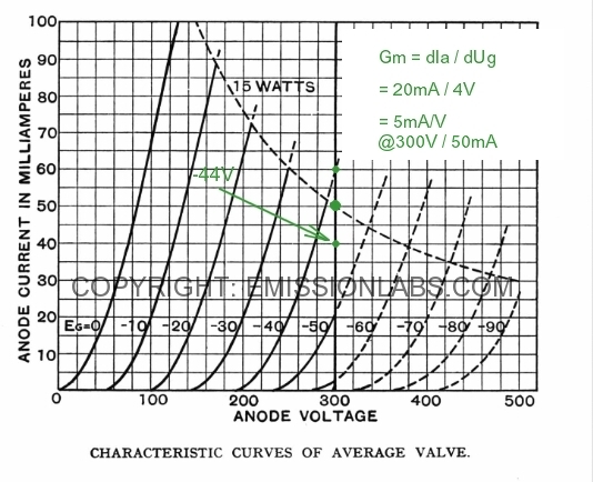
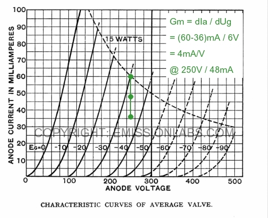
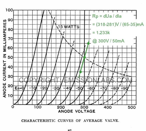
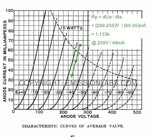
We need to work with what they left us. That is the historical data sheet, and the historical tubes which collectors own. The result was: Ra=830 Ohms, and Gm=6mA/V, but you must keep in mind, this was specified at Ua=100V and Ug=0V. So take good note of this simple combination of numbers, as written in this sentence, and from here the mystery tour begins....
Unfortunately, the datasheet does not give Ra and Gm at the normal operating points. It's simply left blank. Now you don't absolutely NEED to know, because one can indeed determine the desired operating point by using the tube curves only. However historical PX4 is so rare, I don't think any amplifier designer would use an historical PX4 tube, and the historical datasheet, to design his products, and then tries what the replica tubes are doing in his amplifier. Though it would of course be the best way. To get hold of a really fine, historical PX4 you need to know a collector who leaves you his treasure for experiments. Very unpractical of course. So instead of that, they just take a Chinese tube, bias it at 250V, 48mA and there you are: it works. But does it really...?
We have some lovely misunderstandings on the PX4 replica market today. So you will see the Chinese have made a PX4 with 6mA/V because they copied that number from the Marconi datasheet. But... for the working point for this, they obviously thought 100V Anode and 0V grid is not a good idea. So for the working point they used the datasheet recommendation. So there you see: 250V/48mA and Ra is recommended 830 Ohms, so that was what they copied. Only where is Gm? Just look elsewhere and you see: Gm=6mA/V at 100V anode and 0V grid. So now they had Ra, Gm, and a recommended working point.
The mistake
If you can see the mistake already, well done! But many are unaware Gm is a function of the bias point. And not just a little bit. So the Gm data at 100V anode, is totally another at 250V anode. You see here, what plain copying of other's data sheets can lead to. Even so, the Chinese were not the only one, making this mistake. The weird thing is, the Chinese ';PX4'; with it's funny parameters, was used by many amplifier designers, and nobody ever found out, the parameters were in fact wrong. For this, you have to look carefully at the OSRAM Data sheet, and you will see there, Gm is NOT defined as 6mA/V @ 250V/48mA as the Chinese did it. It is 6mA/V @ 100V/65mA as OSRAM did it. And that is a MAJOR difference, and it would be a big mistake of course to ignore this. Any PX4 like this to my opinion should be called a PX3 or a PX5 but not a PX4.
Let's begin at the beginning once more.
We have to admit it, we made initially the same mistake at EML, but then of course when verifying the prototype point by point, versus the original tube curves of OSRAM, the prototypes appeared unsatisfactory. They they were was not really bad, there is always some tolerance of course, but we just could not make a good bogey tube. We even stopped the PX4 project initially.
I am sure you already found this text confusing, and it is indeed. So let's begin at the beginning, and make an inventory in table form of what we know, and what we do not know about the PX4. That will result in the following table, where the red boxes are simply never filled in by OSRAM. I repeat, the background for this, to my opinion for 99% sure, was the AVO MK1 tester.
So here is the inventory of known data. These is all that was published by Osram: (here the original data sheet)
Here is a problem for those tube Manufacturers that want to re build the PX4. Some of the data is missing as you can see. Moreover in the original datasheet, it is indeed marked that Gm , Rp and Mu are defined at 100V anode and 0V grid, but this is written there very confusing. So some day, somebody may decide a PX4 has Rp = 830 Ohms and Gm = 6mA/V. Then this needs an operating point, and there is one for 15 Watt and one for 12.5 Watt. Then combine this 15 Watt operating point, and the result is like in the next table. Now of course you are free to do so, but such a tube differs from to the OSRAM PX4, and that to my opinion that is too far away from a PX4 to call it a PX4. I will explain this more detail, why I think so.
The Chinese result is published like this on their website (Second column)
|
Constructing the missing data from the Chinese curves.
On a Chinese tube manufacturer website, there is a graph they made with the Sofia tester, and they write this is made with AC heater. I do not think so, because I have the schematics of the Sofia, and I own two of them, and they have DC heating, and no option for AC heating at all. They don't have the option in hardware, and not even a correction in software. So, ANOTHER mistake. This doesn't matter a great lot for a tube with -50V Control Grid Voltage, but you are indeed measuring the tube at 2 Volts offset. (Half the heater voltage). Just want to bring this up here, and do the math precisely. Some numbers on that graph were hard to read, so I photo shopped the revised Control Grid Voltage in the graph, including 2 Volts compensation for the DC heating. And now we are getting something, and the result looks like this:
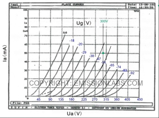
Chinese PX4 on Sofia tube tester, bias point marked by myself.
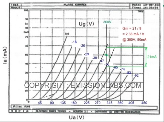
Chinese PX4. Reconstruction of Gm Data
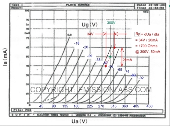
Chinese PX4. Reconstruction of Rp Data
The gain (Mu) can be calculated, it equals: Mu = Rp multiplied by Gm
Constructing the missing data from the 1928 Osram curves.
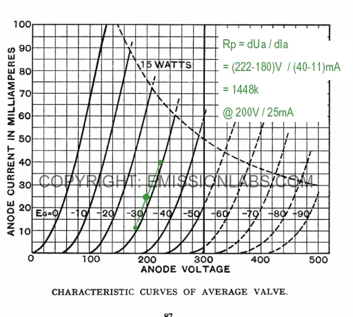
To prove the above graphical construction is the right method, I will do so with the OSRAM data sheet, and reconstruct the values for Gm, Rp nd Mu, at 100V Anode and 0V Grid. The result should be: Rp = 830 Ohms and Gm = 6mA/V
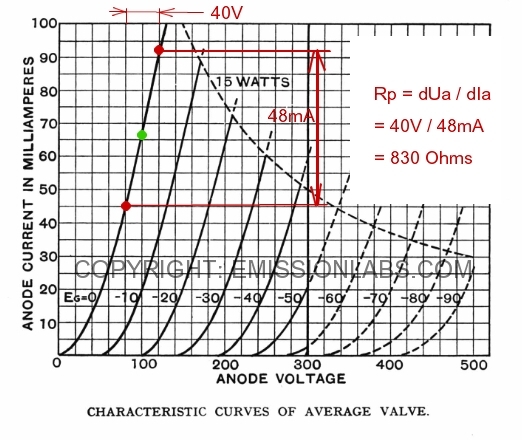
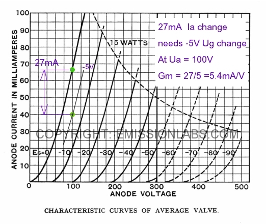
As you can see, I do not fully find 6mA/V but only 5.4 but it has to be said this method of only going down vertically (and not going up as well) in the chart, it gives some small error. However constructing is not possible otherwise in this way, as there is no data in this chart for positive Control Grid Voltage. (Any curves for positive Control Grid Voltage may not be just be penciled in, as dynamic tube data changes suddenly some 10% above +0Volt. You can check that yourself with curves of some triodes that do present positive Control Grid Voltage curves indeed) So, finding 5.4 instead of 6 proves just the graphical construction method is correct, and we know the missing 10% is from not having the positive Control Grid Voltage data available. We don't follow up on this here, as there is no need.
What are going to do: It is possible to construct the data from the normal operating points though, so at 300V and 250V. This will be done in the next charts, and this is going to lead to very precise Gm data, as needed.
Finally completing the OSRAM data sheet after 90 years :) .
We can just re construct the missing data, by using the tube curves.