Emission Labs Data Sheet
EML520B-V2
EML520B-V3
EML520B-V4
Description
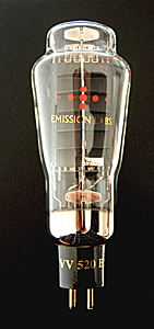 |
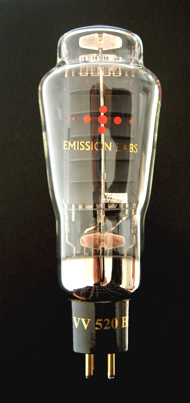
EML520B is a premium tube. It has developed from the older 52B, with many technical improvements added. Two of the most important, the EML520B has extremely stabile bias, and it is also mechanically more rugged. All critical parts, like filaments, grids and Anodes are constructed of hard metal for higher reliability and reproducible quality. Note the relation between the tube base, and and the glass bulb. Then compare this with our 300B. This gives an idea of this tube's remarkable size, which is the same as an 845 tube. |
Guarantee program for first owner.
The first owner can register the tube within 4 weeks after receival, at the Emission Labs website, to participate in the 5 years guarantee program, which is additional to the legal obligations of the seller.
Register here for the 5years guarantee
Features
- Gold Plated Grids (See Notes)
- Soft rubber suspended tube base
- Hard metal Construction (See Notes)
- Extra large getters
- Hand blown Glass bulb
- Anti-microphonic Anode- and grid suspension
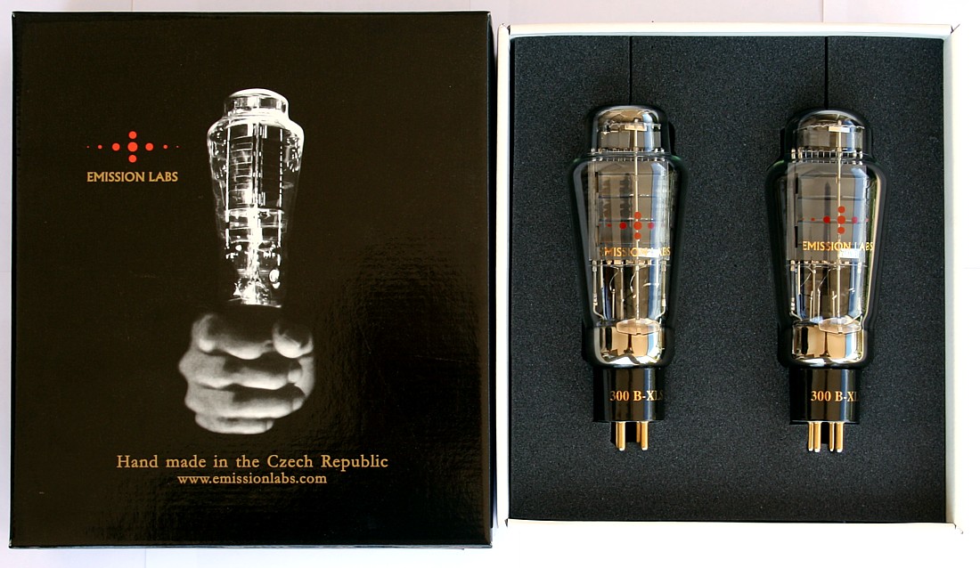
- These tubes are shipped in a high quality dual box
- Tube printing with 24k gold, and red color burned into the glass
- Gold Plated, black ceramic socket
Introduction
Who has designed his own amplifier with 300 tubes, will know that you always end at some point where you would like to increase the working point of the tube. However, with 300B, dissipation should be limited to a practical 32Watt, in order to get good lifetime from the 300B. Still you can try of course at 40 Watt, and you will see it works significantly better. Not only will that give more output power by itself, but also the efficiency of the 300B increases, and even so at higher voltage, distortion becomes less. Here is where the 520B comes in. Characteristics at are quite similar to 300B, but the tube can be biased at a lot more current, higher voltage, and higher dissipation. At higher bias points, which are not possible for 300B any more, the 520B starts to become really alive. The higher output power results not only from the higher dissipation, but also from the higher efficiency of the 520B. It is the universal genius, which can be used as an upgrade for 300B, but also for quite stressful high power designs.Sound Character and use of the EML 520B
1. Use as improved 300B tube
Though this is no drop-in replacement for 300B, it is possible to replace a 300B with this tube, provided some things which must be checked. Care needs to be taken to have the right bias, and also it needs to be sure the heater supply will still do 5V at the higher current of the 520B. (2.1 Ampere vs 1.3 Ampere of 300B). With some knowledge of electronics, these can be used as ultimate upgrades for 300B tubes.
One of the best things of the 520B is the lower Anode resistance (480 Ohms of 520B vs 700 Ohms of the 300B). This will lead to higher efficiency of the amplifier, and a more output signal, even at the SAME bias settings. Moreover the signal will be less distorted at higher volume, The lower Anode impedance will also give better control of the BASS speaker chassis, since the damping factor increases with 25% compared to standard 300B. This will not give so much louder bass, but more natural sounding bass. This can be done with existing 300B amplifiers, provided the technical checks, described in the previous text.
2. Use as large high power 300B tube
In cases where a significant higher bias of the tube is possible, an undistorted 18....20Watt Single Ended power can be supplied by the 520B tube with great ease, or up to 24 Watt as a maximum. This requires dedicated amplifier design.
3. Use as Push Pull tube
The 520B-V3 is very well suited for Push Pull applications also, since the higher peak emission (vs 300B) will ensure much longer lifetime for the 520B. Occasional overload of a push pull amplifiers is sometimes hard to prevent, if the user wants the maximum out of it. Other than with SE amplifiers, the power dissipation of a Push Pull amplifier is very dependant of the maximum output signal, and rises even sharply if driven into distortion. Unlike the previous models (called 52B), the 520B is not immediately taking damage of accidental abuse. Of course we can not specify how far you can exceed the maximum, but the thermal capacitance of the anode is very large, and this is the best protection against accidental (short time) overload. Another protection is the special grid, which will not develop grid current after occasional overload of the Push Pull stage. Last but not least we use a special anode composite, which allows very high dissipation. We do not specify how much, but there is considerable reserve in the specifications of the 520B, making it a very reliable tube despite it's hard use condition.
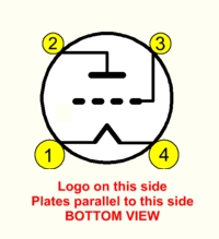
 We have three versions for the heater:
- The older 6.5 Volts heater. (Version V2)
- The newer 5Volts heater. (Version V3)
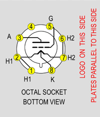
- The Cathode Tapped (balanced) 5 Volts heater with Octal base. (Version V4)
With the Cathode Tapped tubes, we enter a new field of applications. This has not been done before with Audio tubes. When biasing a normal DHT tube, like 300B or any other, there is no cathode to connect something to. The cathode must be artificially constructed, by a resistor network, which is a small compromise. Reason is, inevitably, not just the tube's DC current, but also the complete AC signal current must pass through those resistors, which has some obvious disadvantages. Provided the heater wires are all serialized, we may tap this in the center, and voila: We have our cathode back again. Moreover this behaves like a real cathode. So the V4-tube has an Anode, a Grid, and a Cathode. The centering resistors are no longer needed. For the heater we have connections H1 and H2, and all we need, is a floating 5V connected to it. We took the opportunity, to connect H1 and H2 each with two contacts, to have lower contact resistance. So indeed, we end up with a real, 3-connection triode, and a 5V heater. Now the tube has five wire connections, and for this reason we can not use the 4 Pin UX4 base any more. We have chosen for the Octal base. It must be said, the V4 is a very special tube, which fulfills the needs of Circuit Design purists the best possible way. Depending on how you do it, you can enter new design fields. Or, it is still possible, if you change your mind, connect a V4-tube, the classic way, like any 300B or 520B-V3. In that case, disconnect the Cathode Tap, and connect the remaining 4 wires like any regular Directly Heated tube.
Here is an application note, for how to use the V4 (Cathode Tapped heater) Version.
Please read all notes at the bottom of this data sheet before installing this tube.
Filament Ratings (See note4 and 5) |
|||
| . | 520B-V2 |
520B-V3 |
520B-V4 |
Filament VoltageCan be AC or DC. Tolerance ´+/- 5%. Read also next line, below here. Use only voltage source. |
6.5 Volt |
5.0 Volt |
5.0V with Balanced Heater. ( 2x 2.5V ) |
| Tolerance on filament voltage: With high power tubes, correct heater voltage is the key to long life. We recommend 0.1V above specified voltage on the SOCKET solder tabs. This compensates for small voltage drop across the contacts. Maximum tolerance is +/-5%. This does not mean, anything form 95% to 105% makes no difference. BEST lifetime is achieved at zero tolerance.
|
|||
Filament CurrentThere is tolerance on filament current, we do not specify this, but it can be in 200mA range. A matched pair has always matched heater current. Just make sure the voltage is correct, and then all is ok. |
~ 1.5 Amp. |
~ 2.0 Amp. |
~2.0 Amp. |
EML 520B Capacitance (all versions) |
|
| Grid to Plate | 21pF |
| Grid to Filament | 11.9pF |
| Anode to Filament | 5.6pF |
Maximum Conditions
|
|
| Anode Voltage | |
| Anode Current | |
| Tube Output Power | |
Highest possible Grid to ground resistor, Single Ended. |
|
Highest possible Grid to ground resistor, Push-Pull. |
|
.
EML 520B Factory Test conditions |
|
| Anode Voltage | |
| Anode Current | |
| Control Grid Voltage | Average -102V |
| Transconductance | As Matched |
.
Typical application |
|
| Anode Voltage | 458V |
| Anode Dissipation | 55Watt |
| Anode Current | 120mA |
| Grid DC Voltage | -91Volt |
| Anode Impedance (Rp) | 520Ohms |
| Unloaded Gain (mu) | 6.7 |
| Effective Gain | 5.6 |
Tube Power Output in Class A |
21.6Watt |
| Load Impedance (Ra) | 2600 Ohm |
| Lundahl Transformer | LL1679-120mA |
| Grid resistor to ground | Max. 100kOhm |
.
520B Single Ended operating points | ||||||||
Anode Voltage | Control Grid Voltage |
Anode Current (mA) |
Anode Rp (Ohm) |
Load (Ohm) |
Anode Dissi-pation (Watt) |
Power Output (Watt) |
2nd harm. (dB) |
Recommended Lundahl Transformer |
400 |
-82 |
80 |
530 |
2800 |
32 |
13.2 |
30 |
LL1679-120mA |
400 |
-81 |
100 |
530 |
2000 |
40 |
15.6 |
25 |
LL1679-120mA |
400 |
-80 |
120 |
510 |
2000 |
48 |
18.7 |
25 |
LL1679-120mA |
| . | ||||||||
450 |
-95 |
80 |
580 |
3300 |
36 |
13.0 |
27 |
|
450 |
-92 |
100 |
520 |
3600 |
45 |
14.3 |
31 |
|
450 |
-91 |
110 |
520 |
3600 |
50 |
15.6 |
31 |
|
450 |
-89 |
120 |
520 |
2600 |
54 |
21.5 |
24 |
|
500 |
-106 |
90 |
620 |
3600 |
45 |
16.0 |
32 |
|
500 |
-104 |
100 |
560 |
3600 |
50 |
17.5 |
32 |
|
500 |
-102 |
110 |
560 |
2600 |
55 |
24.0 |
25 |
|
Alternative: Use transformer Impedance Board for LL1620 by JACMUSIC to switch between two output impedances. Board EE18 switches LL1620 between 4 and 8Ohms at 3k3. |
||||||||
Other operating points: For operating points, not given here, you can estimate the parameters by averaging between two rows of this table. Output Power: Specified at the tube, so transformer loss must be subtracted. This is depending on the transformer choice and quality. Low Loss transformers have larger dimensions. |
||||||||
.
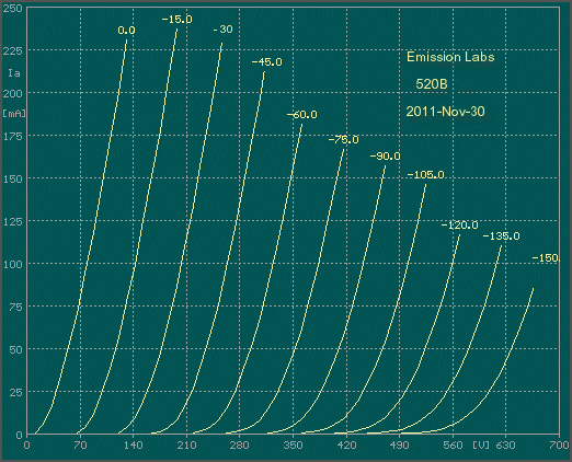
EML 520B Anode Curves
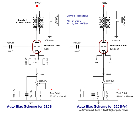
Some suggestions for Auto Bias
EM520B Mechanical DataSize including Socket, but excluding pins: 180 x 68 mm |
|
|
|
|
|
Notes
- This is a heavy power tube, and using it safely means avoid risks. The maximum conditions can be destructive limits, if exceeded continuously. A 'maximum possible' working point exists, but we do not specify it, because it is generally not a good idea to try this out, with any power device, as well as vacuum or solid state. So what we publish here, are recommended working points, for good reliability, optimized sound and safe use.
- Hard-metals can be used in electron tubes, though these are more difficult to use, and more costly than classic nickel. Hard metal Anodes have a more precise Anode distance, and do not change shape when heated, or at mechanical shock. This ensures reproducible tube parameters, and long term stability. Wolfram grids allow the most precise grid wire distance, because wolfram is an extreme hard metal. Best grid geometry ensures uniformity and linearity of the tube curves. Gold Grids is a word generally used for gold Plated grids, so not gold wire grids. The grids we use, are made of specially purified hard metal, which is then thermally Gold Plated. The advantage of gold Plated grids is better temperature stability, and lower grid current if the tube gets very hot, and (within limits) it protects the tube from overheating damage and gives some self repairing effect after accidental overheating.
- Filament current has changed, from June 2005 to the value in this data sheet For tubes of older date, please refer to the filament current value as written on the certificate that is in the original tube box. Please inquire when this data got lost.
- When using a slow-start circuit for the filament, it is definitely not allowed to apply Anode voltage during that time. This voids the guarantee on our tubes. Do not experiment with lower filament voltage, to expect better lifetime. We already specify filament voltage for the best lifetime.
- Individual Test data, such as: Matching Data, Grid Current, Vacuum, Filament Current, etc., are on the Certificate that is on the outside of the tube box. Each tube is numbered from the inside, with a metal Tag
- The curves for this tube are plotted, with AC heating. For DC heating, all grid voltages shift 2.5 Volts.
- Heater voltage is always defined at the tubes pins itself. There may be some voltage drop along the wires, and tube contacts as well. So voltage measured at the tube socket wiring should ideally be 5.1V.