EML 300B-XLS, 300B-XLM Data Sheet
Description
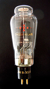 |
This tube has the classical grid construction and the tube curves of the 300B. It has the stronger Anode construction and larger glass of the vintage 52B however. So in one tube we have combined the very best of two classical products.
|
Guarantee program for first owner.
The first owner can register the tube within 4 weeks after receival, at the Emission Labs website, to participate in the 5 years guarantee program, which is additional to the legal obligations of the seller.
Register here for the 5years guarantee
Features
- Gold Plated Grid(Note8)
 Soft rubber suspended tube base
- Hard metal Construction(Note1)
- Extra large getters
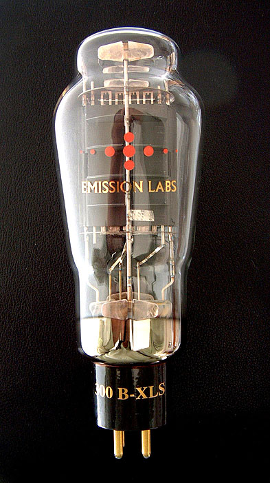
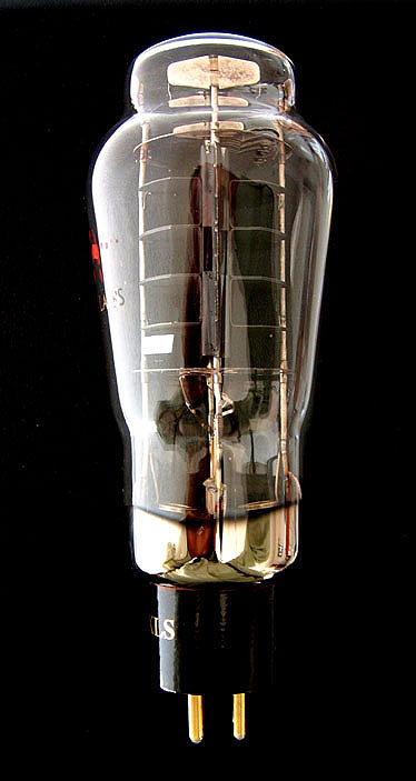
- Hand blown Glass bulb
- Anti-microphonic Anode- and grid suspension
- These tubes are shipped in a high quality dual box
- Tube printing with 24k gold, and red color burned into the glass
- YAMAMOTO tube sockets highly recommended.
- Gold Plated, black ceramic socket
Sound Character of the EML 300B-XLS
300B-XLS is an ideal choice, because good sound results from not over stressing the tube. This means the tube should not be working at the maximum electrical limits. Here we think the 300B-XLS is at it's right place, taking advantage of the higher electrical reserve this tube has. The 300B-XLS will reproduce the required loudness with much more ease than the standard 300B. The result is a more transparent sound picture at low or medium volume, while at higher volume, the dynamics of the original recording will stay unaffected.
Sound Character of the EML 300B-XLM
When a tube is given mesh Anodes, something magic happens to the sound. We believe this is caused by the better damping properties of the wire mesh material. A Solid Plate anode can have some ringing (bell like effect). A mesh anode will not have this effect. In most cases, when using mesh tubes, you will experience a more transparent sound stage. With mesh tubes you will enjoy the very best of what triodes have to offer. in general, we recommend to use mesh XLM at somewhat lower bias as the solid plate XLS. This is better for the tube, and it also develops it's characteristic, somewhat more silkier mesh sound.
Note: mesh means woven metal wire. Chinese factories make a tube with punched metal sheet, and for marketing purposes call this 'mesh'. Which is not so. Such a thin sheet punched Anode, will have a metallic sound, and will miss the damping properties, of the wire mesh anode.
For use in Push Pull amplifiers
300B-XLS is a very good choice, because Push Pull is hard on the tubes by definition. The 300B-XLS is made to deal with such conditions, and will allow the amplifier to play gently at low sound level, as well as reproduce higher sound level with the detail and precision you expect from a push pull amplifier. Even more suited for Push Pull is 320B-XLS.
Bias of the 300B-XLS / XLM
These tubes will bias in any amplifier the same way as the original WE300B. Sill it can be used in two ways if you want it. These two methods are explained here.
- It is possible to replace any 300B with this tube. Just plug it into any 300B amplifier, and the tube will set itself exactly to the original 300B working point. The EML 300B-XLS is a very strong tube,and it will develop the output power with more ease. Specially for amplifiers that let the 300B tubes work very hard, the EML 300B-XLS is the right product choose. Any amplifier that is trying to get as much as possible power out of a normal 300B, will benefit from the 300B-XLS. Improved sound and longer lifetime will be the result.
- Another purpose is to get more power,as would be possible with standard 300B tubes. This can only be done when there is the possibility to adjust the bias of the amplifier higher. If the Anode current of the tube is set ABOVE the standard 300B specifications, the tube will now move to a part of the curves with lower Anode resistance. This is a specialty of the 300B-XLS and 300B-XLM. This will give a better damping factor of the bass loudspeakers, resulting not in more bass, but in a more natural sound. Check our customer feedback section of the website!
- Alternatively the whole amplifier can be dedicated to only the 300B-XLS / XLM, if both anode voltage and current can be increased. A list of recommending working points is given, further down in this data sheet.
We have two versions for the heater:
Normal heater with the UX4 Socket, or Cathode Tapped heater with an octal socket for the 300B-XLS only. Tubes with the Cathode Tapped heater have an additional electrical connection, and need an octal socket for this reason. The Cathode Tap, provides a REAL electrical cathode, which simplifies schematics, improves signal to noise ratio, increases tube output power and lowers distortion. Yet, if desired afterwards, these can always be used as regular 300B-XLS, by simply not connecting the Cathode Tap.
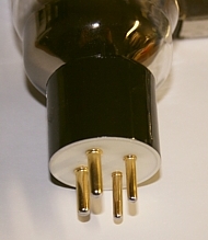
Normal UX4 Socket
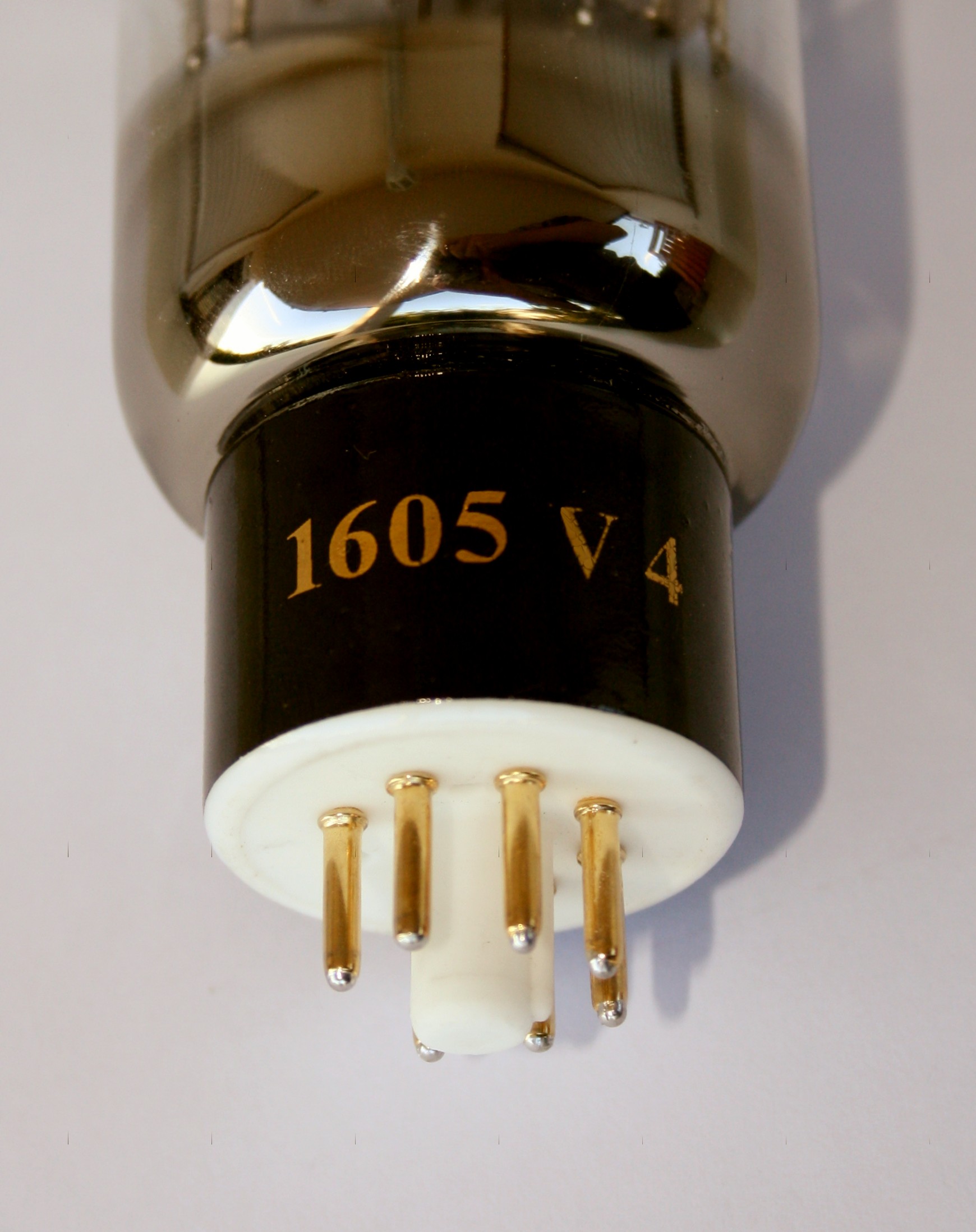
V4-Version with Octal Socket, only availbale for 300B-XLS
Here is a link to Application Note 06, describing the V4-Version in general.
Filament Ratings (See note 5) |
||
Standard tube 300B-XLS / XLM 4Pin Socket (UX4) |
Cathode Tapped 300B-XLS V4 8Pin Socket (Octal) |
|
| Filament Voltage (AC or DC) | 5 Volt |
|
| Electronic heater modules: | Only Voltage Source Current source not recommended |
|
| Tolerance on filament voltage | ||
| Filament Current | ~ 1.5Amp |
|
Factory Test conditions |
300B-XLS |
300B-XLM |
| Anode Voltage | 495V |
400V |
| Anode Current | 100mA |
75mA |
| Grid voltage ( DC heated) | -104V |
-88V |
| Transconductance | 6.4 mA/V |
6.2mA/V |
| Anode Current | 100mA |
75mA |
| Note: these are average values, variation is appr 5% for random tubes. Any other current will also give another transconductance | ||
EML 300B-XLS incoming inspection. Tested at 495V, 100mAMultiply Grid Voltage with transconduction |
|
| New tube | |
Maximum Ratings |
||
300B-XLS |
300B-XLM |
|
| Maximum Anode Voltage | 600V |
600V |
| Maximum Anode Dissipation | 55Watt |
41 Watt |
| Peak Anode Dissipation | 60Watt |
60Watt |
| Maximum Anode Current Fixed Bias |
110mA |
110mA |
| Maximum Anode Current Auto Bias |
120mA |
120mA |
| Recommended grid Resistor for Auto Bias |
100k
|
100
|
| Maximum grid resistor for Auto Bias | 150k |
150k |
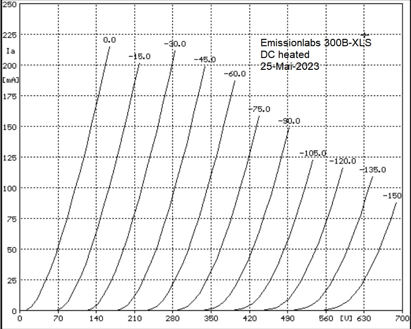
300B-XLS / XLM have the same curves. See Note 3
These Curves as white Print Version
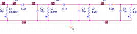
Some recommended Lundahl transformers |
|||
Primary |
Secondary |
Anode Current |
|
3000Ω |
Alt.B = 4Ω Alt.C = 8Ω Alt.D = 16Ω |
90mA |
|
3000Ω |
Alt.B = 4Ω Alt.C = 8Ω Alt.D = 16Ω |
110mA |
|
2700Ω |
Alt.B = 8Ω Alt.C = 16Ω |
110mA |
|
| Alternative: Use transformer Impedance Boards for LL1623 by JACMUSIC. EE16 switches between 4 and 8Ohms at 3k. EE18 switches between 8 and 16Ohms at 3k. |
|||
3000Ω |
8Ω |
80mA |
|
Complete list of recommendations here |
|||
300B-XLS / XLM Mechanical Data
|
|
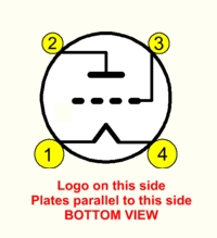 Standard UX4 Base |
Pin 1: Heater1 |
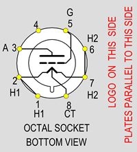 Special Octal Base, V4 Version only for 300B-XLS |
Pin 1+2: Heater1 |
Notes
- Hard-metals can be used in electron tubes, though these are more difficult to use, and more costly than classic nickel. Hard metal Anodes have a more precise Anode distance, and do not change shape when heated, or at mechanical shock. This ensures reproducible tube parameters, and long term stability. Wolfram grids allow the most precise grid wire distance, because wolfram is an extreme hard metal. Best grid geometry ensures uniformity and linearity of the tube curves.
- Individual Test data, such as: Matching Data, Grid Current, Vacuum, Filament Current, etc., are on the Certificate that is on the outside of the tube box. Each tube is numbered from the inside, with a metal Tag
- Average Plate Characteristics are made with the Sofia Digital Curve tracer.
- The Western Electric 1950 Data sheet. says 36 Watt maximum dissipation. Later data sheets say 40 Watt. Though 40 Watt is possible, this is a peak value only, and no normal working point. When you intent to get the 'maximum' out of a 300B, and operate this tube at the limits of safe operation, it is a much better idea to use the 300B-XLS in such a case.
- Some of our competitors claims to be the only one with a Center Tapped filament, but at EML we build since many years all tubes Cathode Tapped, not just this tube.
- Do not experiment with lower filament voltage, to expect better lifetime. We already specify filament voltage for the best lifetime.
- Gold Plated grids have a few advantages, such as increased bias stability, some protection against accidental overload, and better linearity of tube curves.
- The curves for the 300B-XLS are plotted, with DC heating. These are also valid for the 300B-XLM.
- Heater voltage is always defined at the tubes pins itself. There may be some voltage drop along the wires, and tube contacts as well. So voltage measured at the tube socket wiring should ideally be 5.1V.