Saving the world from Solid State
Data Sheet
12B, 20A, 20B, 20B-V4, 30A
Description
This is a series of tubes with medium gain, with with very good voltage capabilities, and very low distortion even at high signal.
Applications |
||||||||
 |
ANODE TYPE |
Driver tube |
Line Out |
Speaker Output |
OTA |
Head Phone |
Sakuma |
|
12B |
Black Powdered |
Yes |
Yes |
Yes |
. |
Yes |
||
20A |
Mesh |
Yes |
Yes |
. |
. |
. |
||
20B |
Black Powdered |
Yes |
Yes |
Yes |
Yes. |
|||
20B-V4 |
Black Powdered |
Yes |
Yes |
Yes |
Yes |
|||
30A |
White Powdered |
Yes |
Yes |
|||||
Guarantee program for first owner.
At EML we have the normal guarantee. In addition to that, the first owner can register the tube within 4 weeks after receival, at the Emission Labs web site, to participate in the 5 years guarantee program.
Register here for the 5years guarantee
Features
- Gold Plated Grid. (See Notes)
 Soft rubber suspended tube base
- Hard metal Construction (See Notes)
- Extra large getters
- Hand blown Glass bulb
- Anti-microphonic Anode- and grid suspension
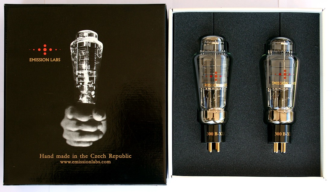
- These tubes are shipped in a high quality dual box
- Tube printing with 24k gold, and red color burned into the glass
- Gold Plated, black ceramic socket
12B
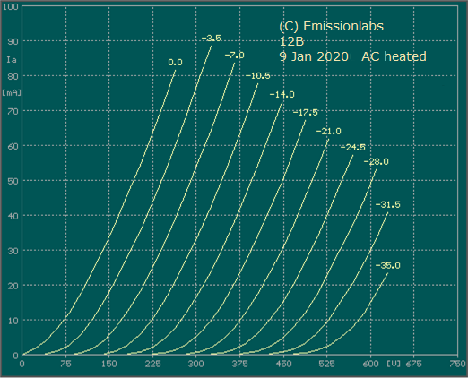
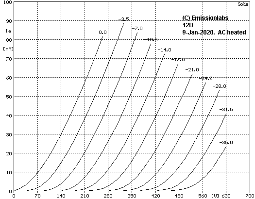
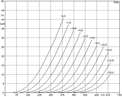
This tube has gain of appr. 12x, and medium-low impedance. It can be used in almost any application, including speaker output at almost 5 Watt. Also, beautifully 12B can be used as a SAKUMA amplifier, using a 12B to drive a 12B speaker tube. This tube has sound resemblance to the vintage PX25, due to curve similarity.
20A
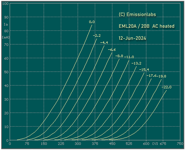
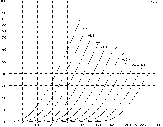
This is a mesh tube, with gain of appr. 20x, and medium impedance. It has a very pleasant triode sound, due to nearly total absence of odd harmonics. It's application is a driver tube for medium signal.
20B
This is a solid plate version of the 20A. It works well in all 20A circuits, but can also be biased higher as 20A. At medium voltage it is a wonderful driver tube. For lower signal it may be used at low anode voltage, like 250V. At higher anode voltage, up to 580V, 20B becomes capable of delivering very high output signal, as required for instance to drive the 845 or GM70 tube. Also at higher voltage it can deliver a few Watts output power. It can be used as driver tube or low power output tube.
20B-V4
V4 means only the heater wire has a center tap. This gives a fifth connection, so this tube needs an octal base. It is compatible to the classical 20B, but offers the advantage of the center tap on the filament. The center tap, provides a real cathode connection, for a simpler circuit, yet with better performance. Application Note AN-6 explains the meaning of the V4 Version.
30A
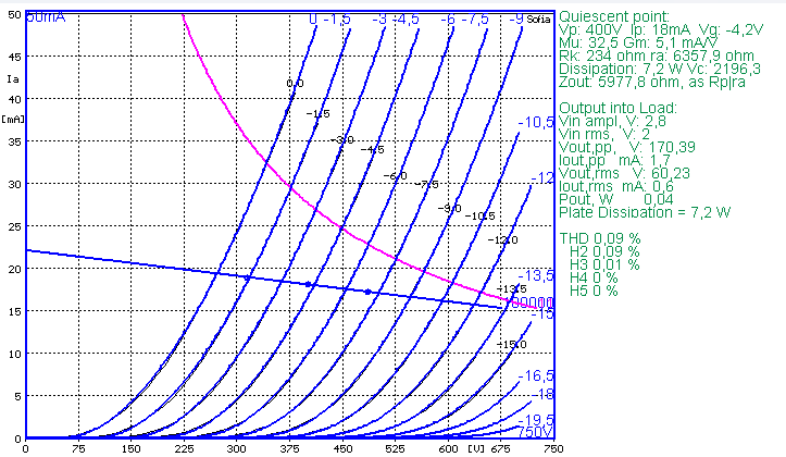
The 30A has an unloaded gain of appr. 30x. It is intended to combine the driver and pre-amplifier tube in one. This tube has exceptional low distortion, below 0,1% 2nd harmonics, and 0.01% 3rd harmonics, at FULL signal output of 60Volt RMS. Here is a print of the simulation program, to show this. This program used these 30A tube curves, measured with the Sofia curve tracer. At lower signal, distortion drops even further.
Filament Ratings |
||
Standard tube 12B, 20A, 20B, 30A 4Pin Socket (UX4) |
Cathode Tapped 20B-V4 8Pin Socket (Octal) |
|
| DC voltage recommended | = 5Volt |
= 2.5 - 0 - 2.5Volt |
| Electronic heater modules: | Only voltage source |
Only voltage source |
| Tolerance on filament voltage | 5% |
5% |
| Filament Current | ~ 1,4Amp |
~ 1,4Amp |
Maximum Conditions(See Notes) |
EML
|
EML
|
EML
|
EML
|
| Anode Voltage |
500V |
490V
|
580V
|
500V
|
| Anode Current |
60mA
|
40mA
|
60mA
|
40mA
|
| Continuous Anode Dissipation |
25Watt |
11Watt
|
25Watt
|
11Watt
|
| Grid resistor |
below 470k
|
below 470k
|
below 470k
|
below 470k
|
Factory Test Data |
EML
|
EML
|
EML
|
EML
|
| Anode Voltage |
390V
|
400V
|
420V
|
400V
|
| Anode Current |
40mA
|
25mA
|
42mA
|
25mA
|
| Anode Impedance (Rp) |
2k9
|
3k7
|
3k
|
6k2
|
| Amplification Factor |
13.5
|
21
|
21
|
32
|
| Transconductance |
5.6 mA/V
|
4,2mA/V
|
6,9mA/V
|
5,2mA/V
|
| Control Grid Voltage
Tested with DC heating |
-16V |
-7.4V |
-5,6V |
|
| Control Grid Voltage Tested with AC heating. |
-9,9V |
-8,1V |
||
|
||||
12B Some operating points.This is AC heated. If DC heated, Grid voltage shifts 2.5 Volt. (See Notes) | |||||||||||
Anode Voltage | Grid Voltage |
Input |
Cathode resistor for Auto Bias |
Anode Current (mA) |
Circuit Gain |
Tube Ri (Ohm) |
Load (Ohm) |
Lundahl Trans former |
Output |
Tube Dist. Total |
Use as |
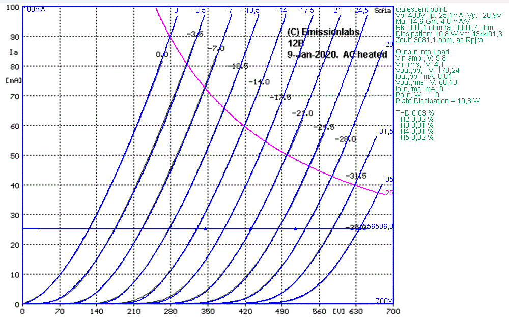
430V See Chart |
-20.9V |
4.1V RMS |
831R |
25mA |
14.6 |
3k1 |
Choke or inter stage |
LL1668-25mA |
60V RMS |
0,03% |
Driver Stage
|
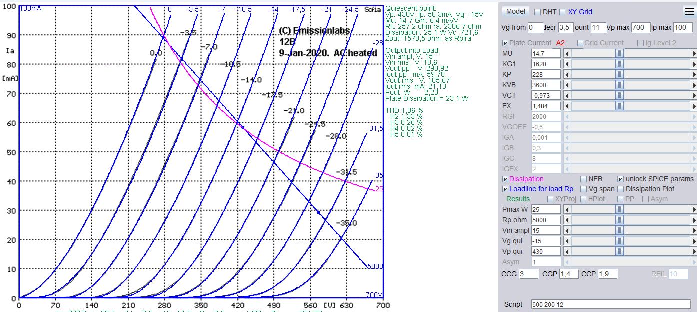
430V See Chart |
-15V |
10,7V RMS |
257R |
58mA |
10 |
2k3 |
5k |
LL1663-60mA |
2,2Watt |
1.4% |
Output Stage |
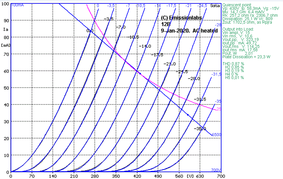
-15V |
10,7V RMS |
257R |
58mA |
10.8 |
2k3 |
6k5 |
LL9202-50mA |
2Watt |
0.9% |
Output Stage |
|
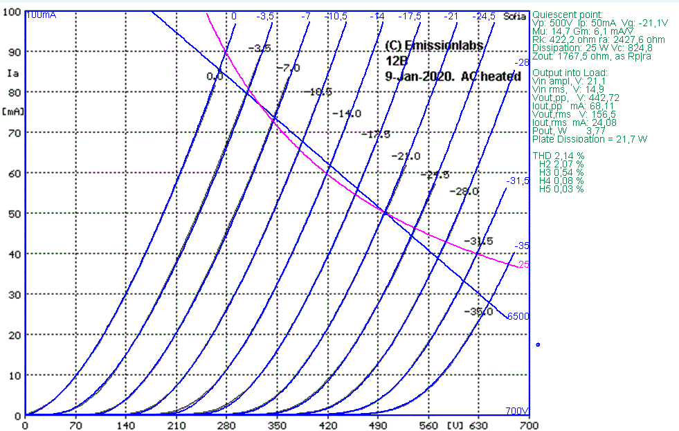
500V See Chart |
-21.1V |
14,9V RMS |
422R |
50mA |
10 |
2k4 |
5k |
LL1663-50mA |
4,1Watt |
3,3% |
Output Stage |
500V See Chart |
-21.1V |
14,9V RMS |
420R |
50mA |
10.5 |
2k4 |
6k5 |
LL9202-50mA |
3.8Watt |
2.1% |
Output Stage |
| As a driver stage, most power tubes like 300B, need appr 60V RMS on the grid. Using 12B as a driver, only 4.1V is needed. This can be achieved with a 4x step up transformer, which gives this gain free of noise and microphonics, and supplies even a balanced input. | |||||||||||
20A Some operating points | |||||||||||
Anode Voltage | Grid Voltage |
Input RMS |
Cathode resistor for Auto Bias |
Anode Current (mA) |
Circuit Gain |
Tube Ri (Ohm) |
Load (Ohm) |
Lundahl Trans former |
Output |
Tube Dist. Total |
Use as |
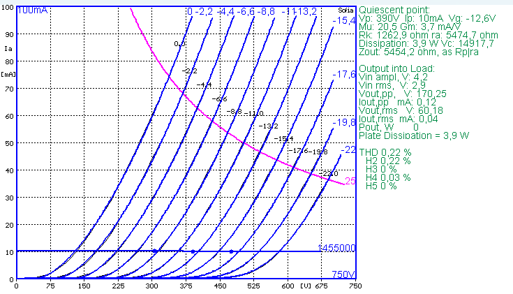
350V See Chart |
-12.6V |
3.14V |
1263 |
10mA |
20.8 |
5k4 |
Choke loaded |
LL1668-10mA |
60V RMS |
0,17% |
Driver Stage |
| For full output signal, most power tubes like 300B, need appr 60V RMS on the grid. This is 170 Volt peak to peak, and it needs good consideration how to generate such high signal free of noise and distortion. Using 20A as a driver, only 3.14V is needed. This can be achieved with a 3x step up transformer, which gives this gain free of noise and microphonics, and supplies even a balanced input and no further drive tube is needed. | |||||||||||
20B Some operating points | |||||||||||
Anode Voltage | Grid Voltage |
Input RMS |
Cathode resistor for Auto Bias |
Anode Current (mA) |
Circuit Gain |
Tube Ri (Ohm) |
Load (Ohm) |
Lundahl Trans former |
Output |
Tube Dist. Total |
Use as |
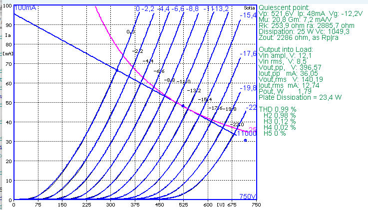
521V |
-12,2V |
8.5V |
254R |
48mA |
16.4 |
2k9 |
11k |
LL9202-50mA |
1,8Watt |
1% |
Output Stage |
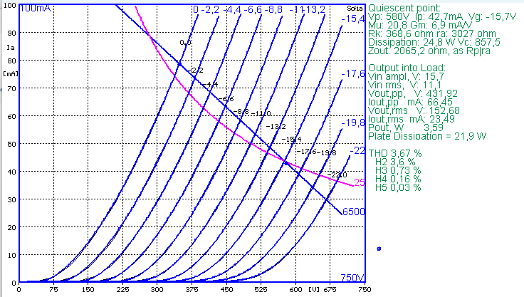
580V |
-15.7V |
11.1V |
368R |
43mA |
13.4 |
3k |
6k5 |
LL9202-50mA |
3,59Watt |
3.7% |
Output Stage |
LL2935B |
Output Stage |
||||||||||
30A Some operating points | |||||
Anode Voltage | Control Grid Voltage
|
Anode Current (mA) |
Trans-
|
Tube Ri (Ohm) |
Gain
|
300 |
-3 |
10 |
4.6 |
8k |
36 |
300 |
-2 |
15 |
5.3 |
6k6 |
35 |
300 |
-1 |
20 |
5.5 |
5k9 |
33 |
.
| |||||
360 |
-5 |
10 |
4.4 |
8k |
36 |
360 |
-3.8 |
15 |
5.1 |
6k9 |
35 |
360 |
-2.8 |
20 |
5.7 |
6k |
34 |
360 |
-2 |
25 |
6.2 |
5k6 |
34 |
360 |
-1.1 |
30 |
6.6 |
5k1 |
34 |
. |
|||||
420 |
-6,7 |
10 |
4.3 |
8k5 |
36 |
420 |
-5.6 |
15 |
5.0 |
7k |
35 |
420 |
-4.6 |
20 |
5.5 |
6k |
33 |
. |
|||||
480 |
-8.6 |
10 |
4.1 |
9k3 |
38 |
480 |
-7.5 |
15 |
4.9 |
7k2 |
35 |
480
|
-6.5 |
20 |
5.5 |
6k3 |
35 |
|
Size including Socket 155 x 58 mm Single Tube weight: Shipment weight for pair in gift box: |
|

Notes
- Hard-metals can be used in electron tubes, though these are more difficult to use, and more costly than classic nickel. This ensures reproducible tube parameters, and long term stability.
- Individual Test data, such as: Matching Data, Grid Current, Vacuum, Filament Current, etc., are on the Certificate that is on the outside of the tube box. Each tube is numbered from the inside, with a metal Tag
- Plate Characteristics are made with the Sofia Digital Curve tracer.
- We are recommending the same values as Western Electric in their 1950 Data sheet.
- Some of our competitors claims to be the only one with a Center Tapped filament, but at EML we build since many years all tubes Cathode Tapped, not just this tube.
- Do not experiment with lower filament voltage, to expect better lifetime. We already specify filament voltage for the best lifetime.
- Gold Plated grids have a few advantages, such as increased bias stability, some protection against accidental overload, and better linearity of tube curves