5U4G Mesh Data Sheet
5Z3 Mesh Data Sheet
Description
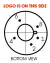
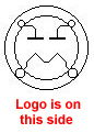
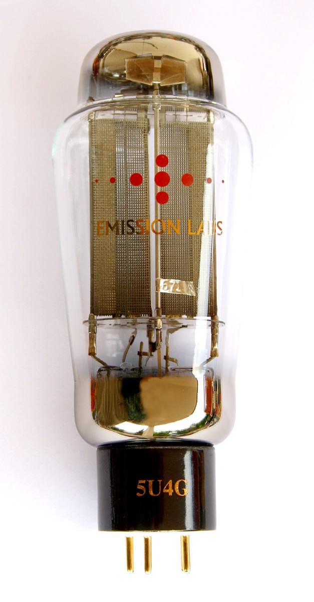 This data sheet applies for the 5Z3-Mesh and 5U4G-Mesh, which are electrically identical, apart from the sockets. 5U4G-Mesh uses as Octal Socket socket, of which only five pins are used (and one of those is electrically not connected). 5Z3-Mesh uses a four Pin UX4 socket.
These are direct replacements for the historical 5U4G or 5Z3. They can not replace 5U4GA or 5U4GB which are different tubes. See Note 4
Note that the Emission Labs® tube is somewhat larger size than the historical tubes. Check below at mechanical data, for details. Like most NOS rectifiers, also the EML rectifiers are Slow-Start tubes, protecting the power supply and the whole amplifier to some degree. The delay time for first function is 2 seconds, and the delay for full current is 7 seconds.
For ultra low ripple, it is recommended to use the Lundahl LL1673 dual coil choke in low CMR configuration. In this configuration, there is virtually no field radiation from the choke. (See link to circuit diagram, at the bottom of this page).
Guarantee program for first owner.
At EML we have the normal guarantee. In addition to that, the first owner can register the tube within 4 weeks after receival, at the Emission Labs® website, to participate in the 5 years guarantee program.
Register here for the 5years guarantee
Features
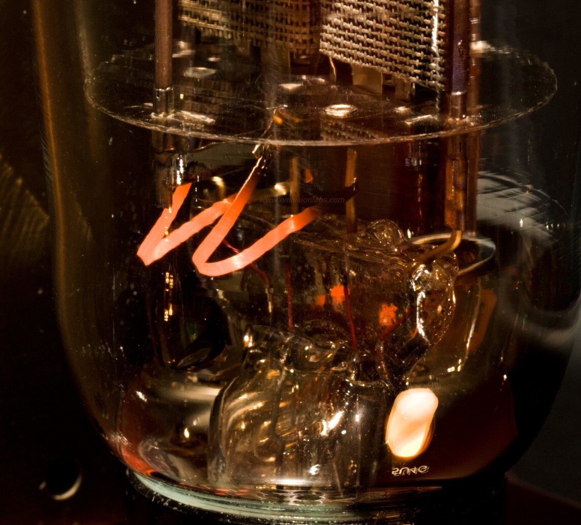
- In 2011, we have included inside the tube glass a special element to stabilize the heater voltage. See also the pictures on the right. (or here) These elements at higher current, will increase their resistance, and help protect the heater against accidental over voltage.
- Slow Start ( 2...7 seconds)
- Filaments are series connected, for best symmetry of the two diodes inside.
- Extra large getters.
- Each tube is numbered, inside the bulb with a metal Tag.
- Extra large getters, flashing the complete tube bottom.
- These tubes are shipped in a high quality box.
- Tube printing with real gold (metal), red color is burned into the glass.
- In 2011, we have started to ship 5U4G-mesh with the new ceramic socket, with five pins. From Yamamoto, the Octal 8/5p Teflon socket is recommended. This is an octal socket, but has five pin holes only. It is specially used for this rectifier. When working with Octal sockets, you will find the Yamamoto an amazing top class product. For this rectifier you can take the special octal version with five holes only. Like this you can never put in a non-rectifier tube by mistake. You can also use normal octal sockets of course.
Filament Ratings |
|
| Filament Voltage | |
| Tolerance on filament voltage | |
| Filament Current | |
Maximum ratings
|
|
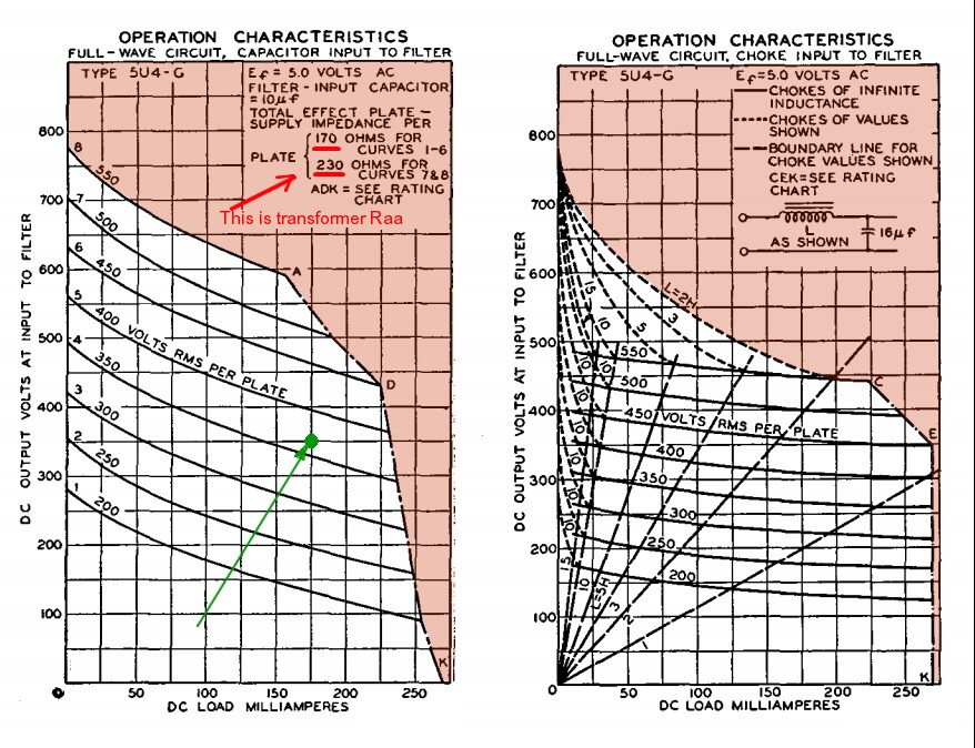
| AC transformer voltage | 550Volts |
AC transformer copper resistance (Raa) |
Not below 170 Ohms for curves 1...6 Not below 230 Ohms for curves 7...8 |
| DC output current of circuit | 225mA Capacitor loaded 265mA Choke loaded |
| First capacitor, connected to Anodes | 40uF |
| AC Peak Current (repeatedly) | 800mA |
| Transient Peak Current (only once) | 4A |
Mechanical Data |
|
|
Tube Size including Socket: Connections:Filaments: 8 + 2Anodes: 4 + 6 |
|
Tube Size including Socket: |
Tube weight |
|
Shipped weight for one tube |
|
PART II
DESIGNING RECTIFIER CIRCUITS
Typical application
- > See: CIRCUIT DIAGRAM
- > See: Note 2
Left Chart for following Capacitor loaded tube, with these values: |
RIght Chart for following Choke loaded tube, with these values: |
|
|
About these Charts:These charts are graphical design tools, saving the trouble of calculations. Both charts show some degree of derating, meaning you can not have maximum current and maximum voltage at the same time. As the choke loaded circuit is not so hard on the tubes, you will see derating is less at very high current. So the maximum of 265mA can be used up to 350V DC output. This is definitely not possible with a capacitor loaded circuit. Though capacitor loaded circuits perform good at low to medium current, like at 100mA you can get 600V, where choke loaded will only do 470...540V depending on the choke inductance. This is only from the view of convenient use. From the view of good tube life and smallest hum field radiation, choke loaded is preferred, unless you work at very low current, like below 75mA. From the right choke loaded chart it can be seen, the maximum current of 265 can be used to generate 350Volt DC, whereas the capacitor loaded circuit at 350V can only so 230mA. Yet when generating 480VDC, the limit is 150mA only of choke loaded, or 200mA capacitor loaded. It pays off to check, if you can fulfil the needs with a choke loaded circuit, and if yes, this would be the better circuit to take. So both circuits can do 480V at 150mA, and choke loaded will sure do this at less disturbance to sensitive circuits near by. How to use these Charts:
|
|
These graphs are from the historical RCA data sheets. When designing new circuits yourself, be aware a tube rectifier is more difficult to use than a silicon diode. Very roughly, the electrical model of a tube rectifier is like an ideal diode, with a resistor in series. You need to limit the peak value at any circumstance to prevent defects, and keep it as low as possible for best lifetime. Since peak current is difficult to measure, a more practical way is use graphs such as the one on the left here. All in the end, you will notice you need more than a quick glance on the data. You will always end up with some sort of de-rating. Such as: At maximum voltage, you can not draw maximum current. At maximum current, you can not use the maximum first capacitor. Maximum tube life will not go together with maximum load conditions, etc. Mistakes come from now knowing how these compromises must be made, or copy circuits from the internet, made by others the same way.
Choke loaded circuit.
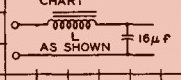 The best for the tube, and for low hum field radiation, is a choke loaded circuit. In simple wordings, a capacitor loaded circuit is lower cost, but will put more stress on the tube, and also some stress on the first capacitor, which will degenerate by this over the years. A choke loaded circuit will put the stress mainly to the choke, which is a device with no wear out, and the tube and capacitor are spared a lot.
Technically there is more to it. A choke loaded circuit will force almost DC current through the diodes. Moreover, a choke loaded circuit acts as a 'DC transformer', so the DC current which is generated, it higher as the AC current used! To make it even better, a choke loaded circuit has a better load regulation as capacitor loaded. So at higher current, voltage drops less as with a capacitor loaded circuit. This may all sound unbelievable, but it works like this: The inductance of the choke is a constant current user, or constant current supply, either way, depending if the transformer is charging the circuit, of if the circuit is discharging itself into the load. When the inductance is large enough, the DC current change very little within one AC cycle. So a signal almost like DC will flow trough the choke, and for that reason through the entire circuit. This includes the rectifier diodes, and even the transformer windings. The engine storage buffer for this is the choke itself, which will generate the required voltage, to keep the DC current flowing. Like this, the whole circuit carries DC current. The function on the second capacitor is to prove an L-C filter to reduce residual hum, but AC current peaks of the capacitor are small. Much to the contrary of an C-L-C circuit, which has a very heavy pulsed charge current into the first capacitor. This current with C-L-C circuit can radiate a magnetic field, saturate the mains transformer at it's peaks, and also wear out the rectifier diodes much faster. The much more gentle L-C circuit. can load a mains transformer up to 100% of it's specified ratings, wheras C-L-C circuits can load a transformer only up to 66% (or the transformer will produce audible hum + magnetic hum field)
We much recommend you to have a look at the original RCA data sheets, winch content is too extended to quote it here, however this is the one and only reference for designs with a long tube life. Designs with mistakes in it, will initially work. So the fact it 'works' does not prove you will get long lifetime.
After all, the disadvantage of a choke loaded circuit is the cost and dimensions of the choke. So many times, you will see HiFi companies saving money on it.
Please note it can not be the intention here, to explain how to design a good circuit. However we try to tell some things here, that we know are sometimes not looked at very well. Also we encourage you to read the original old data sheets. from RCA, General Electric and Sylvania, and Telefunken. You can download these and a lot more s from 4tubes.com. So look there for datasheets, and the famous RCA handbook
Some important things to remember (unsorted)
- Fuse Protection. To protect the rectifier, a slow fuse must be used. If choke loaded, the fuse must be from the output of the DC voltage, to the rest of the circuit. If capacitor loaded, the fuse must be to the transformer Cathode Tap. (So where there is a wire to the transformer Cathode Tap, inside this wire must be a fuse inserted)
- The ideal application of ANY rectifier tube, all brands, is Choke Loaded. A choke loaded rectifier circuits will give better performance in many ways, however it's function is often misunderstood, and for this reason not often used. However we recommend a choke loaded circuits with first priority always.
Advantages of a choke loaded rectifier circuit, vs. capacitor loaded are following:
- >Transformer HV winding can be used up to specified maximum output power, instead of 66% de rated value for capacitor load. This is so for all transformers, any brand. Otherwise heavy mechanical hum may appear. In other words: A 100 Watt transformer winding may be loaded only with 66 Watt of capacitor loaded, or 100 Watt if choke loaded. Choke loaded circuits are almost a resistive load for the transformer, whereas capacitor loaded circuits cause impulsive load (with rattling noise).
- >Longest lifetime of the rectifier
- >Less AC field radiation from the wiring
- >Very lower internal resistance of the output voltage, when above 1/3 of maximum output current. This will make the DC voltage independent of the current drawn, within 10%. Capacitor loaded rectifier circuits provide no load regulation, and drop the output voltage rapidly at higher current.
- >No need to deal with transformer windings resistance
- If Capacitor loaded, you must have a minimum required copper resistance of the transformer winding.
This old design rule, is still obligatory for any 5U4G, EML or other brand. If capacitor loaded, the first capacitor must be chosen at or below the maximum value in this data sheet. At EML we adapted to the same values from old data sheets. So there will be no doubt about those values. The minimum resistance is specified for the complete winding. (So not measured from the Cathode Tap). In case you use a transformer with too low copper resistance, you need to add one series resistors in each HV winding connection of the transformer. Then, with those two resistors in series, you re-measure the transformer winding, and the result must be as follows:
Raa, value, for Curves 1...6: minimum 170 Ohms
Raa, value, for Curves 7...8: minimum 230 Ohms.
If you ignore this design rule, tube damage will result. Also in many 'professional' amplifiers, this design rule is not used by designers who do not read the historical data sheets Tube damage can result as a white spark inside the tube at switch on, filament material can chip off, or the tube life will be much reduced. With most amplifiers, the transformer winding is directly connected to the tube socket, and no protective series resistors are used. In most cases, the transformer resistance can be conveniently measured by a specialist, directly at the tube socket, when the rectifier tube is removed first. - Never operate the tube in the red area of the graph, above.
Note the graph has a white and a red (pink) area. Operation in the red area is strictly forbidden. Going to the limits is possible, but maximum tube life will not result from this. The '70%' limit for long-life operation applies also here.
When studying the graph, you will see a dotted line, on the right upper side. It looks like a corner of the graph is cut off here. This cut off piece will be larger when the first capacitor is larger. So now, it is specified for a first capacitor of 10uF in this graph. The best way to prevent problems, is not the maximum value capacitors, and use simply a bit higher transformer voltage and larger chokes to get the required result. This will not give less efficiency of the rectifier circuit ! It will however make any type of rectifier tube last longer. Even the opposite effect can be seen, when people over-rate the first capacitor in an attempt to get lowest possible hum. In several cases, over-rating the capacitor will even increase the total hum of the amplifier. Elementary design rules say, you stabilize a high voltage with a large choke, and low voltage with a large capacitor. With maximum value capacitors, the capacitor charge pulses get extremely high, causing hum field radiation into the pre-amplifier wiring and tubes. These charge pulses have a kind of 'bad sounding' wave shape, and smallest hum field radiation from this, can become audible if strayed into the pre-amp circuit anywhere. Two design notes for this are at the end of this data sheet. When designing your own circuit, you should really read those notes.
Notes
- Note 2) To prevent large charge current peaks, the first capacitor (C1) should NOT be larger than 40uF. If the input capacitor is too large, this will result in heavy AC charge current through this capacitor. This is not good for the rectifier tube, and also not for the capacitor lifetime. The AC capacitor current peaks may cause hum radiation into the preamplifier. With the given C-L-C values in table, the rectifier circuit will work best. For filtering, with oversized components, you will have best results by increasing the choke. Do not oversize capacitor C1, this may increase hum. You can choose the choke large as you want. This will have better results with high voltage rectification.
- >Note 3) Rectifier tubes may under no circumstance carry larger current peaks as what they are designed for. The current peaks are mainly a function of: power supply DC load, first capacitor and transformer copper resistance. The copper resistance for 5U4G and 5Z3 may not be smaller than 170 Ohms. This is very important to check, and too low copper resistance may damage the rectifier, no matter what brand or construction. Use a small series resistor if the copper resistance of the used transformer is too low. If you scroll further down this data sheet., there is a link to a table with historical information about this, for several rectifier types, not only 5U4G.
- >Note 4) There is common misunderstanding that 5U4G and 5U4GB is electrically the same. 5U4GB is a version, with lower internal resistance and higher peak current is allowed. The GB version is not the same tube as the G Version. Replacing 5U4G with 5U4GB may result in higher rectified voltage, so should never be done. Replacing 5U4GB with 5U4G may result in lower rectified voltage, and may result in damage of the 5U4G rectifier.
- >Note 5) For those who do computer simulations, the Anode current of 5U4G can be found by Child-Langmuir's Law. This results in the formula Ip=K*Vp^1.5 You can enter this in programs and draw a Anode curve. The number K is the Diode Perveance, the value is in Amps per Volt, that tells nicely what that means. That you have to find experimental with new tubes. It was found for new 5U4G as 0.000777