Technical Bulletin 08
The right way to TEST Electron tubes.
For Emissionlabs, this is an important information page, about the best way to test tubes. Please be not angry about some clear sayings here and there, but we see so many mistakes with testing of tubes, it is painful.
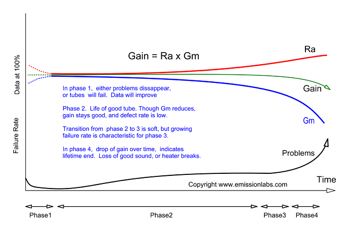
Tube lifetime and wear out.
Testing of tubes is quite a misunderstood item. Tubes have some phases during their life time.
- The new born phase, where they are not burned in. At this moment, they are not at it's best yet. There may be some small grid leakage, some noise, peak emission is not at it's highest, and some more minor issues. All of which is normal in this phase, and also sound is not as good as it could be, because the curves are not ideal yet.
- The mature phase. After burn in, all these above weaknesses have disappeared. The tube will stay at maximum conditions for a long time now, provided the heater voltage is EXACTLY right. So not at the limits of what is allowed, but exactly right. This will give the ideal balance between evaporation of the active Barium layer, and regeneration from within, from the Barium Oxide depot, which lies underneath the Barium Layer. This is the secret to maximum life time. During this phase, the tube parameters will change, but only marginally.
- The end-of-life phase. This begins, when the Barium depot of the cathode is getting depleted, and inevitably, the emission will now begin to reduce. Such a tube can often be used still for a long time, if the tube is not used at the edge of the possibilities. When the peak emission is not present any more, but at the same time is not required in the amplifier, the tube will stil work good. Historic tube testers have the '?' range for this, indicating the tube can normally be used if it appears to work well. Though Gm may be reduced, gain is still the same.
- Final phase. Gain of the tube reduces The tube needs to be replaced because of volume loss, or heater breakage.
Testing procedures
Most DIY prefer to test tubes with fixed grid voltage, because tube testers can do this more easily, and it simplifies everything. Even so, some companies who develop a tube tester, do the same, but this is unprofessional.
What is important?
1) AVOID fixed grid voltage for tube testing.
This is not in line with any data sheet ever printed, or test instruction. No tube manufacturer said so. Not historically, and not today.
Results will be wrong for several reasons. The most important parameter of all, is transconductance (Gm), because a CHANGE in transconductance indicates some wear out. So not the absolute value indicates this, but the change in original value. For this reason, we write this value on the box of each tube, and of course the test conditions for this. (Testing for Gm at other conditions, make the compare inpossible)
It seems widely unknown, that Gm is a function of the plate current, Actually the variation is very much, and there is no such a thing as 'the' Gm of a tube. There is only the Gm at a specified plate current. There is no Gm at a specified grid voltage. Ignoring this, so simply use fixed grid voltage and measure Gm anyway, will of course give you a Gm value, but you can not do much with it.
To measure Gm the correct way, you need to change the grid voltage, until the tube has the data sheet plate current, and THEN measure Gm. Doing this the right way, or the wrong way, can give differences of 30% easily. Which is dangerous, because you might think Gm is at 80%, while in reality it is at 100%. Or you would measure Gm is at 100% while the tube is in reality at 80%. Such errors take place, when fixed grid voltage is used for testing.
2) If the anode is only heated up only by the cathode heat from inside, tests results are unreliable by definition, or may as well be INVALID.
What do we mean by this, and why do we say this?
The tube tester market is flooded with so called impulse testers, which do test the tubes indeed at the specified voltage and current, but the test impulse is only for 0.001 second or so, and the rest of the time, the tube is off. The idea of such testers is, to save on the power supply, which in a professional tester makes up most of the cost. The only source of heat is the cathode, and no heat comes from the anode. Such testers are not useless of course, but they suggest a LOT more (fake) precision as they really have. The reverse is also the case. If no errors are found, that does not mean the tube is good. Such devices for this reason can not be called tube testers, because of this reason. They are called curve tracers. Please note, many severe tube errors only appear at 80% dissipation or above. Such as thermal runaway (the #1 killer for power tubes), but also parameter drift, cathode leakage and grid emission, just to name a few.
Any heater to cathode leakage tested with a cold anode, is plain bullsh... If an impulse tester presents a number fro cathode to heater leakage, or Grid current, either the designer of the tester knows not what he is doing, or he is fooling the user, but any other options I do not see. By definition these tests should only be done when the tube has reached it's final maximum temperature, which takes five minutes under maximum plate dissipation, and even so you need to wait longer if the tube appears to have drift. A test for drift of no drift, needs half an hour at maximum dissipation, It is really foolish to believe a tube is 'good' when not testing it at full anode dissipation.
Just seriously suppose I have a quad of NOS KT88 for sale, which fails at maximum dissipation, but tests excellent at an impulse tester. Would you say it these are good tubes? Probably not! You would not accept the fail at maximum dissipation. But when tested with an impulse tester, nobody asks for a test at maximum dissipation. The test is done at maximum power, sure. But only for 0.001 Second, and that gives no significant plate dissipation at all.
About EML tubes
Here are the categories of tube testers for as far as I know, which can be used to test EML tubes. Placed here is order of usefulness.
- Good vintage testers for testing EML tubes, are the Neuberger 370,375. The 'Sofia' by Audiomatica is the Queen of tube testers for me, but unfortunately, lvery few were ever made. Funke W20 is good, and also AVO VCM163 with adapter socket for UX4 tubes.
- Roe-test, by Helmuth Waigel is top class. There is nothing like it from new production.
- Amplitrex AT1000 can have position #3. Provided you know how to use it in PC mode. I have seen several times people disputing the need for using the PC mode, and (what a coincidence....) not having the skill for this as well. However using it in computer mode is mandatory to bypass it's many bugs and failures. When you only press the 'test' button in the stand alone mode, you will get a wrong results in many cases. I will write some more about this, further along this page.
- Useful vintage testers, though these can not verify the EML at high voltage. Such are: Kalibr L1-3, L3-3, Hickok cardmatic, Metrix U61B. Probably several others. Such testers can at least be used for tubes which need maximum 250 or 300V plate voltage.
- Impulse testers can not detect dissipation related failures, and by definition indicate plate current and Gm somewhat too low, at insufficient anode temperature. They are nice for curve tracing and parametric data, but not for precision testing.
Forum babble vs data sheets.
Of course users become confused with all of this, but the greatest confusion to my opinion results when people who do not know, ask other people who also do now know. Don't do that! At the same time, when somebody knowledgable on forums brings good facts, it is regarded an opinion only. This behavior, to prefer to listen to amateurs, seems to belong to the world of HiFi. I have really given up trying to understand this. The best source of information is always what the manufacturer writes. You are still free of course, to regard manufacturer information biased. Just it becomes strange, when the manufacturer's instruction is opposite. A red warning lamp should to burn, when people are presented clear engineering facts, and they say, they do not believe that. What they are saying is, they did not understand it.
A good data sheet.
For understanding how a good data sheet is written, there is no replacement for studying some good and bad examples. A bad example is JJ ECC803S though you may initially like the simplicity. But it is wrong for ECC803S, which is a life time specified tube, with specified acceptance limits and specified end-of-life limits, to ignore all of this, as JJ does. A much better example is Telefunken ECC803S. Or a excellent example for professional audio tubes, is TELEFUNKEN C3g. It pays off, trying to understand WHY they write the things they write in there. So not try to understand the tube curves of the C3g data sheet, that is not what I mean. Try to understand the structure of the data sheet. Because it was written for YOU, for the user. So read for instance also how Telefunken ECC803S, in the original data sheet. I am not interested in any other recommendation as Telefunken says. Telefunken does not say: USE AUTOBIAS. But they say: THIS is the cathode resistor for testing. And THIS is the grid voltage you must apply, and THIS is the plate current for a NEW tube, and THIS is the plate current for an end-of-life tube. Now look, these are clear instructions, Not only print the curves and give only average data for ECC803S, like JJ is doing. Also take good note, they do NOT say you must use a fixed grid voltage. Read this in detail, and draw the test circuit they say. You will then see, it is auto bias!
What else can they say. You really need to read the TELEFUNKEN C3g data sheet, and draw for yourself the auto bias circuit which is needed to test C3g, exactly the way they say it. The break through for yourself will come, when you realize this is an auto bias circuit indeed, and understand how this circuit works. After that you will realize how wrong fixed grid voltage testing is. Not only because (I hope you noticed...) no manufacturer on the world ever wrote you have to test tubes with fixed grid voltage. But because fixed grid voltage will not reflect the Gm of the tube at the INTENDED bias point.
So far, for this much too long introduction.
At Emissionlabs, all we can do, is say how to test our tubes.
Contents
- Short instructions for testing of EML triodes
- What causes misunderstandings
- Fixed current Testing vs. Variable grid voltage.
Short instructions for testing
EML Tubes must always be tested at the VOLTAGE and at the CURRENT as we say. This can be done with a classical auto bias circuit, but it may also be done with a tester, or some other set up with variable grid voltage, such that the SPECIFIED CURRENT is set exactly. At this CURRENT, all other parameters have to be tested. Most of all, Transconductance and grid leakage, and for who is interested, Gain and Plate impedance can be tested during the same test.
Furthermore, testing should only be done after thermal balance. So, directly after adjusting the anode current to the EML specified value, it can be seen it begins to change slowly. This may take some 5...15 minutes, and only when the tube is fully warm, including the socket part, the test results become significant. This means the anode current has to be re adjusted until it becomes stabile.
Here is the same instruction, listed in steps.
- Set anode voltage for value as on the tube box
- Adjust grid voltage such that Anode current becomes same s on the tube box.
- Now tube begins to warm up, and specially power tubes become very hot after 5...10 minutes. This heat is needed for correct results.
- Keep on re-adjusting grid voltage until anode current stays stabile for a period of 1 Minute or longer. Tube may take 5...10 minutes or more to reach.
- Precisely CHECK heater voltage. What counts is the voltage on the metal of the tube pins, not the socket wiring. Voltage drop across socket contacts and wiring can be 0.1 ...0.2V for tubes like 2A3, and 0.1V for 300V. Practically speaking, the voltage source for 2A3 tubes should be 2.6 (or 2.7) Volts for that reason, and 300B should be 5.1 Volt at the source. High Quality tube transformers use those voltages too, in order to compensate for loss of the wiring and socket contacts.
- After tube has become thermally stabile, read grid voltage needed for this. Value may be lower (less negative) as on the box. If this happens to an unused tubes, it means only the tube was stored for a long time, and needs burn in. This will become visible, if the tube slowly begins to grow it's anode current, each 15...30 minutes, it will become a few percent higher. Unintended perhaps, the user is now in the middle of a burn in process. This process may be continued for as long a needed, until no change takes place any more. Practically speaking for EML tubes this takes not very long for unused tubes.
End of Life
If even after longer waiting for final stability, the INITIAL parameters appear to have changed. The user who sees this, wants to have a life time prediction. What counts for this, is the CHANGE of those parameters, compared to initial values, which are written on the box.
We see it over and over again, that 'specialists' which build tube testers, know nothing better to do, than comparing random tubes with data values as published, while testing the tubes with fixed grid voltage. This is so dead wrong. THIS IS WRITTEN NOWHERE. IN NO LITERATURE, AND MOST OF ALL, IN NO MANUFACTURER's DATA SHEET. This is ignoring the fact, that a data sheets represent only average data. As you will see, im those average settings, not only the grid voltage is fixed, but also the anode current, and the anode voltage. So from this alone, you may as well use fixed anode current (called auto bias) and see what grid voltage that needs.
This for instance is from the RCA 2A3 data sheet. (Link here):
But this applies for all 2A3. Anode Voltage 250V, Grid Voltage -45V, Plate current 60mA. Please check for this, you will quickly find it.
Where does it say: Grid voltage must be 'fixed' and plate current is variable? It does not so say this anywhere! You may as well say plate current must be fixed, and grid voltage is variable! Please look up the original data sheet by RCA! At EML we can not speak for RCA, but we should not 'read' things from their data sheet, which RCA has not written.
The use condition of a tube depends mainly on the change versus the initial factory values.
Some suggest that any tube which is not 'average' has a certain 'problem'. Well, this may indeed be so. But you see, it may as well not be so, because you can not tell. This is why this method is so wrong. It tells you not much. A 2A3 which appears to have only 50mA (vs average 60mA) can be totally unused and it was only born that way, due to anode distance tolerance.
If so, such a tube will have normal lifetime as any other. In the same way, an unused tube may appear to have 85mA, suggesting it has 140% lifetime, or whatever this 140% is supposed to refer to. Also this will disappoint you, if you think such a tube well last shorter. You see, if it was that easy, to prolongate tube life by building them with too small anode distance, in order to have them test at 140%, all manufacturers would have done so ever since. Things don't work that way.
That is why we invest so much time here, explaining what is the the right way to test tubes.
How to estimate the remaining life time of tubes.
Wear out of a tube takes place in four phases as follows:
- The required grid voltage, needed to bias the tube at the factory plate current, becomes less negative. This is normal, and indicates only use. Wear out and use is not the same. Use hours may be significant, and yet wear out can be low. Use hours can recognized by this change in required grid voltage in the very first place. Though a small loss of transconductance goes along with this, mainly the grid voltage changes, and this can begin to take place after some hundreds of hours already.
- The above phase continues for quite some time, during which the tube would test strong still. At the end of this phase, a loss of transconductance begins to occur but no loss of plate impedance yet. Now the tube enters the third phase soon
- In this third phase, plate impedance begins to rise. This is a beginning wear out, though the tube will still work, and this phase can take quite long as well. As long as the gain is not changing, the tube is still in this phase 3, and for this reason (gain=ok) it will work good in most applications. The next phase is characterized by loss of gain.
- Gain of the tube is the multiplication of plate impedance and transconductance. For a very long time, the plate impedance will marginally go up, while transconductance will marginally go down in the same rate. This keeps the gain constant. The lifetime comes near the final phase however, when also gain begins to reduce. Not only the natural function of the tube (Gain!) begins to get lost, simply problems will accelerate now very fast, sound problems will soon appear.
Some important informations
- Measure Gm with a tone of 1000....2000 Hz.
- Grid current (g1) can ONLY be measured at maximum dissipation. Any lower dissipation, and not warm up time less than 5..10 minutes, makes no sense and such a test result is invalid.
- If tubes are nor burned in yet, factory data after storage may occasionally have changed slightly. Yet, this will always recover quickly after some hours of use. So in case of doubt, run the tubes some hours at the voltage and current as indicated on the box.
- Compare Gm values by the values as ON THE BOX. The only important thing for wear out, is a change of the initial (factory) values. Which is individual, even for a match pair it may not be fully identical.
- Gm 90...110% = Ideal
- Gm above 80% = Strong
- Gm above 70% = Good
- Gm above 60% = '?' Range
- Gm below 60% = Bad.
What causes misunderstandings
- Impulse testers, such as utrace and e-tracer are unable to heat up the anode. This makes results imprecise, and plate current may test too low. Grid emission current can not be tested this way, as this requires a fully hot tube at maximum allowed dissipation.
- Users take average data from the data sheet, and expect a random tube to test as average Which is never the case, because random is not the same as average.
- People confusing Emission with plate current. Emission is maximum 100%, but plate current if far above 100% is an tube error.
- The difference between testing for quality, and testing for parameters.
- Set a tube for fixed grid voltage, so any random Ia will occur.
- AC heating vs DC heating
Fixed current Testing vs. Variable grid voltage.
Our target is to offer tubes that are well matched, in a way which can be verified by others. At EML we begin with factory testing, which is for emission, for quality and for data limits. Then match the tubes on the AT1000. We are not using the AT1000 because we think this is the best tester. It is not such a good tester at all. Only it is the most widely used tester. And though AT1000 has many shortcomings, it can actually be used for matching, if you know how to bypass the errors is makes by default.
AC Heating vs DC heating.
Tubes can be tested either way. Just test result is another for DIRECTLY heated tubes. That is because half the DC voltage effectively influences the grid to heater voltage. So a directly heated tube will give another result, if DC heated or AC heated. (If DC heated, the tube will draw less current at the same grid voltage)
EML Test method:
- At EML, we had to choose for a method which most users can reproduce. This was DC heating. DC current is tested only after thermal stability, and testing transconductance with a tone signal. These things the AT1000 can do. Use Anode voltage and Current as on the tube boxes
- Use Auto bias testing when your tester can do so, otherwise, set tester by hand to specified current.
- Warm up the anode under those conditions for 3...5 minutes.
- Measure grid voltage needed, and Transconductance resulting from this.
Test result for Gm (2). Small expert talk
This is an ever lasting subject. There are a few methods, which differ by precision of the result. We begin with the best method.
- Transconductance is a dynamic parameter, so to say an AC signal parameter. For best accuracy, it is s measured by applying a distortion free sine wave signal to the tube, with an oscillator, and then monitor the output signal of the tube, while using a band pass filter. Testers like the Russian L1 or L3 testers are doing this, and some other high class vintage testers. The reason why this is the best method, is any distortion elements from the output signal gets filtered out, as these come in the form of higher harmonics. Also any hum and noise is filtered out. So hum, noise and distortion make the output signal artificially too large, any make the output signal (and so Gm) look larger than it is.
- An oscillator method which uses no filtering, is better than non at all, but it is not ideal.
- A lower class method is just use a DC change on the Grid 1, but this doesn't filter out any of the above mentioned signals, and some testers suffer a drop of the plate voltage in such a case too. So in case of any difference with the first method, it is clear where it comes from.
- By software, it is possible to derive Gm by calculating it via the Barkhausen formula, but that may have resemblance with method 3. However when with clever algorithms it may be possible to make it look more like method 1.
How Gm depends on the working point ( a lot)
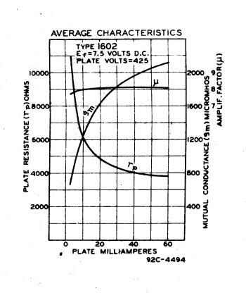
Keep in mind, Gm depends heavily on the plate current, as you can impressively see from the curve on the left. This is from the 1602 which is nothing but a better 10Y by RCA.
As you can see here, Gm varies from 520 to 2100 depending on the plate current. So a huge difference of 1:4 So it should be clear when somebody says he 'has measured Gm of 1600', this by itself has nothing to say. Also results from tube testers, saying 'this is the Gm' but not saying the working point are meaningless too. If this Gm of 1600 was measured at a plate current of 60mA, the tube is bad, and when measured at 10mA, a Gm of 1600 is very high. . From this it becomes evident that saying 'this tube has Gm of 1600' is a useless information, as long as we do not know the plate current. The Gm value can only be compared with the data sheet at the SAME operating point where the data sheet specifies it. So as long as you aware of these potential error sources, it is ok. It would be totally wrong however to measure Gm at any random current, like done with fixed grid voltage testing, and then compare this with the data sheet value for a bogey tube.
Why fixed grid voltage biasing is useless for tube testing.
Here is a numeric example. The tube in this example is the RCA 10Y (1602 special). The data sheet specifies Gm of 1330 at 10mA, which should happen with an average tube at a grid voltage of -23.5V and 10mA plate current. Of course no two tubes will have average values. In order to compare Gm of an unknown tube with the data sheet value of 1330, you need to set this tube for 10mA, by adapting the grid voltage to whatever value is needed.
It would be wrong, to set the grid voltage to simply -23,5V because there is no 'must be' for this value. In fact, plate current is so variable, that minimum and maximum values are not even NOT specified that way. So it becomes totally silly to measure plate current still, and compare it with the average value of a bogey tube. Any 100% strong, factory new tube, at -23.5V will draw anything from 7 to 14mA. So it would be wrong, to let the tube draw whatever current from 7...14mA, measure Gm at that plate current (whatever it is), and compare this with Gm plate current at 10mA.
Seeing this from anther perspective, you can test a tube at any place on the Gm curve you like, but not compare such a measurement with another one, which is NOT on this curve. Logically, the only way to synchronize this, is by testing any 10Y at 10mA, and compare this with the curve at the left at 10mA. Or, alternatively do the whole process at 20mA or any other current you like.
Having understood the above, it should be clear, a Gm measurement should be made always at the data sheet specified DC current, and never at a specified grid voltage.
Using the Roetest
This is the Roll Royce amongst the new production tube testers. It comes close to the Sofia, but it is a kit. You can't buy it as a ready made product. If you can afford it, take this one,
Using the AT1000
LINK to Important Note for non-USA users of AT1000
This is written here is some detail, because we use the AT1000 at the factory for the data on the tube boxes. We do not do so, because it is such a good tester. The reason is, it is commonly used, and indeed it is one of the very few testers that can test under full anode power. AT1000 from before a certain date, have errors in the internal data tables for all directly heated tubes. Please communicate with Amplitrex directly, how to repair this. (We are not a service address for them) However when you set the tester to AUTO BIAS, which is required to repeat the factory test, this problem plays no role anyway. However you will soon see, sometimes (not always) tubes that test 'strong' on Auto Bias, may test 'weak' on Fixed Bias, or vice versa, so you can already see one of the methods is not right. Use only: AUTO BIAS.
AT1000 Stand alone mode or computer controlled mode.
Make good note, the stand alone mode has generally lower precision, because the tubes warm up only the heater, and not the anode, before a measurement.
Stand Alone mode
- It is a pity this tester is factory delivered in Fixed Bias mode. Users have often no idea this test method is generally invalid for 99% of all tubes ever made, including all EML.
- Stored in the tester is a tube data table. If the tube is missing, you have to add it first, which is not difficult. Refer to the manual, so you know how to do this.
- Configure the tester in general for AUTO BIAS. This is most important, not just for EML tubes. (In FIXED BIAS mode, Gm results will be INVALID as a matter of principle)
- Verify if the tester uses indeed the same Anode Voltage and Anode current as we have on the tube boxes. Other settings are possible, for Research purposes, but can not be used to verify factory data or condition of the tubes.
- At the end of an AUTO BIAS test, the result will be: The Grid voltage (-Ug) and transconductance (Gm). If the tube is new, this complies with the factory test data on the box.
For higher precision, the computer controlled mode should must be used, which allows heating up of the entire tube until thermal stability occurs, which is the only really good way to test a tube. For new tubes, the difference between stand alone more and computer controlled mode will be small. Used tubes however, benefit more from thermal stability. So, a quick test in the stand alone mode, will make used tubes look less good as they are.
Refer to the manual, so you know how to do the following:
- If a tube is missing, add it with the tube editor program. Alternatively use 'set up' files This allows changes easier. So you can use a standard 300B setting, but save individual plate voltage or current as a so called 'set Up' file on your PC. This would apply for instance nicely to a 300B-XLS. However at printing is prints then '300B' is tube number. To prevent this, add 300B-XLS to the data base with the tube editor program.
- Always choose 'Auto Bias' before testing.
- Begin by choose only 'Noise Test'. This heats up the tube. Make sure, no multiple tests are selected. Start the noise test, and observe the anode current in the AT1000 display ALL OF THE TIME. This will make the tube very hot. Stop the test when Anode current rises more than 10% above the expected value.
- If the test had to be stopped, restart the test right after. This will set anode current to 100% again. Each time re-start the test when Anode current rises more than 10% above the expected value. After 3...5 times the tube becomes stabile, which can take 5...10 minutes.
- You can use a head phone during that time, and check noise. After a total of 5 minutes the tube is thermally stabile.
- f done, exit stop the noise test, and do the 'Tube test' immediately after.
- Now -Ug and Gm is tested under the specified anode current, and results should correspond nicely to the tube box.
Using full power analog testers, DC heated
This should repeat EML test data precisely. We have tested this with the Russian L3-3 and it works nice.
Using full power analog testers, AC heated
This should repeat EML test data precisely, as long a you correct the grid voltage for half the heater voltage. We have tested this with the Metrix U61 and it works nicely. Unfortunately it limits at 250V DC. (and a little bit outside if you try with an external voltmeter) Yet it can do not many large tubes.
Using E-tracer or uTracer
Please click here to read under Impulse testers.
Using the Sofia curve tracer
Mentioned here to honour this tester, but you can not buy it anymore. This tester has a possibility to heat the tube under full power. After this, a 10 curves chart is made in just a few seconds. The result is, all points of the curve charts are made with a fully hot tube. No other tester I know of, can do this. The AT1000 takes a few minutes for a full tube chart, and while doing so, the tube cools down, and the charts become jeopardized by that. This is why the Sofia is our one and only favorite for tube charts. It can deliver unusual high RMS power to a tube. Unfortunately such a tester is not made any more. The lowest class are impulse testers, which are not capable of heating up the anode at all. The AT1000 at least can heat up the anode before you begin with a chart.
Using the Russian L3-3
This is a perfect one. Measurements have reference quality. Unfortunately it is limited to +300V, but when using an external voltmeter, and not too full DC current, it can be used above 400Volt, provided you have the right test cards for this. We have test cards for EML 5Z3, 5U4G, 80, 81, 274A, 274B, AZ4, 2A3, 2A3-Mesh, PX4-mesh, AD1, 300B, 300B-Mesh, 20A, 20B and 20B-V4.