Replacing 52B tubes by 520B tubes
Last Update:
Description
 The original, genuine specification of the 52B was created by AVVT. Heater voltage and power limits of the AVVT 52B were sometimes changed by them however.
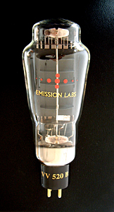
Today, with AVVT not existing any more, we offer similar tubes by EML. To prevent confusion with the AVVT "52B" part number, we do not use this designation. We use 520B-V1, 520B-V2, 520B-V3, and 520B-V4. The V stands for Version.
Which version you need to the replace 52B, we can of course not say without knowing what was used in your amplifier. So saying "It is a 52B Amplifier" is not enough information. Now, with the part number '52B' being gone, this gives more sensibility to the end user, what replacement to choose.
Some notes about quality: Early EML versions from before 2005, and all AVVT products, were easily damaged by accidental overheating. This is forbidden by the data sheet anyway, but it case this happens by mistake, the tubes might take damage. In that case, grid damage, and instable bias can result from this. The instable bias, by itself will cause anode overheating, and this damages the grid further. Then, this results in more instability, and such a tube becomes a trouble maker. EML tubes after 2005, in case of accidental over heating, if not too long time, have a good chance to survive this without damage. Though we can not say here, this is simply possible to do without taking a risk. it seems though when they are still good, that is probably what they are.
520B Data Sheet
Some small help table
|
Item |
What does this mean? |
Remarks |
| Are you a experienced with this item? - Then skip this part and skip to the next. |
Experienced means you need no help. |
Schematics we can supply for as far as we have them. |
| 52B |
Part number first used by Vaic-Valve in 1995. Later by KR. EML used to make it too, but we obsoleted the part number, nor the tube. This was to prevent further confusion. |
52B was subject to many changes in filament voltage an current. Great confusion under users. |
| EML520B-V1 |
Smaller version of 520B. Obsolete. |
Use V2,V3, or V4 instead. |
| EML520B-V2 |
6.5 Volt version of 52B, but all parameters are slightly different |
. |
| EML520B-V3 |
5 Volt version of 52B, but all parameters are slightly different |
Recommended for new designs |
| EML1605 |
5 Volt tube. Larger than 520B, and a possible candidate to replace a 52B, BUT.... it is not the same tube. 1605 needs a the Anode-to-filament voltage of be 500V or higher. If you do not have this voltage, better use 520B-V3 |
Not directly intended at 52B or 520B replacement, but in several cases this is possible still. |
For experienced technicians:
Disclaimer: These are minimum requirements that need to be done, regardless of all other things a qualified technician will have to do. We can not guarantee in any way that this process is free of errors. Please understand this not intended as a correct guideline for amplifiers we have never seen, not build our self, and we do not have the full schematics of. It is just how we probably would do it our self in our own workshop.
You need to find out some things about the amplifier:
- With a pen, write LEFT and RIGHT, on the old tubes.
- Do not work on the amplifier with the tubes vertically. This may cause a grid short. Make some construction, to place the amplifier upside down, with the tubes inserted still.
- Some amplifiers have digital ampere meters inside. These easily damage by over-current. Here is the standard modification, to prevent damage. Before you start, solder a fuse of 100mA inside one of the leads to the Ampere meter. A good place is, simply with one end soldered on PCB. So remove the lead from the PCB. Solder the fuse on that place with one end, and solder the wire to the other end of the fuse. .
- Connect a short circuited RCA connector to the inputs, and short circuit the speaker outputs with a piece of wire. This protects the output transformers against mistakes. For hum test, connect a head phone to the outputs instead, and put back in the short when you are done. This must be a low impedance head phone. If not available, connect an 8 Ohms resistor in parallel. Tube amplifiers are short circuit proof when there is no signal input. However they can damage quickly, when you have no speaker connected. Never leave the outputs open, when you are servicing this amplifier.
- Make sure you do all these things at the one and only correct mains voltage. That is the one it will be connected to at the end user. That voltage may be another one as in your workshop. When you have +5% higher voltage, and the end-user has -5% lower voltage, we talk about 10% which is a not acceptable. So take care with this, and use a Variac.
- Check the filament voltage with the OLD tubes in the amplifier. If they are not glowing, you have defective electronics, or a broken heater. If the heater voltage on the left and right tube are not identical, they may have been swapped by the owner. If swapping does not result in the same voltage, these are replacements put in, without adjustments done. Be very careful when you notice this, as you have a wrong adjusted amplifier in front of you, and other mistakes are possible too.
- Do you know how to adjust the bias current? If yes, reduce the bias to minimum. If no, find this out first.
- If all is ok, with the previous points, you find the heater voltage to be 5V, 6V, 6,3V or 6.5V. Choose EML520B-V3 for 5V filaments, and EML520B-V2 for 6.5V filaments. Adjust any 6V or 6.3V heaters to 6.5V or 5V. Try what is possible, and prefer 5V, so you can use the standard tube, which is EML-520B-V3. If you can adjust only to 6.5V, use EML 520B-V2. If you can not adjust to either 5V or 6.5V, you need to change the electronics amplifier., so you do get the one or the other voltage. Do all of this with the old tubes, so you take no risk with the new ones. The replacements come in later, and you need to re-adjust the voltages with the new tubes inserted. First continue now with the next point.
- Does the amplifier have stabilized filament voltage, and a voltage change is needed, this is possible by exchanging parts. Does this amplifier have adjustable filament voltage, but it is unstabilized? Such as with many older VAIC, KR and MASTERSOUND? This requires special attention. First reduce bias current to minimum, with the old tubes still inserted. Then try one new tube at a time, and test filament voltage right at switch on. Switch off immediately when it is more than 10% off. Re-adjust and try again. When ok do the other tube.
- Now set the bias. If you don't know the correct value, you have a problem, but a good technician has ways to work around this anyway, and set the amp correctly still.
- Now set the hum adjustment pots. These are often well hidden, for instance behind little printed circuit boards which are upside down in the amplifier. So all you see is a tiny hole in a printed circuit board. On the other side is then the pot meter, invisible. Check these pots for good function, they can be broken. If it hums in any position set them in the middle for the time being, but you do need to get a situation where the amp responds to the setting. Final setting is done after burn in
- When you have the bias set, check again the filament voltage, because these often interact with each other.
- When you are ready, let the amplifier run without signal and monitor the bias carefully for 30 minutes. If it goes up or down a little, that can be caused by mains voltage changes. Re-adjust only when more than 5% off.
- Check bias now every 30 minutes for half a day. Re-adjust bias when more than 5% off.
- Check bias now every 2 hours during one day. Never let the amp run without supervision. Re-adjust bias when more than 5% off.
- Now comes 50 hours burn in during which time the amplifier should be stabile. Do not get mislead by any changes caused by mains voltage changing. This is why you should use a Variac. Check as needed, and do final bias adjustment, and final hum pot adjustment.
- Now comes a hearing test. If ok, the work is finished.
- Questions? Only when we can answer it quickly. The amplifier manufacturer is your help desk.
|
Recommendation for filament TESTING.
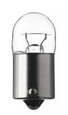 Do not use the expensive EML 520B tubes as an experimental load for modified circuits, or self made circuits. They are too expensive to be used as a fuse. Just use a 6V, 10 Watt lamp instead. On 5V it will be approximately the same load as the 520B. When this works well, then you can remove the lamps and use the 520B instead, and adjust them nicely for the correct heater voltage.