Emission Labs 520B Tube
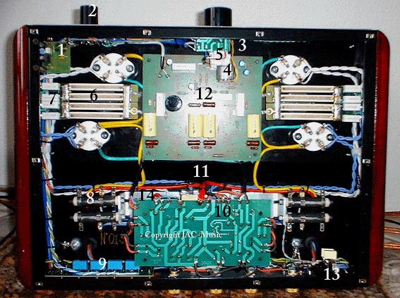
Replacing of 52B tubes in amplifiers of KR, VAIC, Mastersound, and others |
Data sheet of EML520B |
| Replace tubes in 52B or 520B Amplifier. | Tube Data Sheet |
Replacing of 52B tubes in amplifiers of KR, VAIC, Mastersound, and others |
Data sheet of EML520B |
| Replace tubes in 52B or 520B Amplifier. | Tube Data Sheet |