Technical Bulletin TB-11 Part 2
Cathode-Issues
by Jac van de Walle
The white Spark Problem. PART 1.
The white Spark Problem. PART 2.
These notes are not intended for end-users.
Please have your amplifier manufacturer read this, in case of a spark problem.
When do we have a risk on a white spark?
We often see the typical situation, so called 'switching effects' do not behave as intended. Switching effects often behave much different as one may expect, caused by things which ARE in fact very normal, but do come unexpected to many users. Some random issues are (unsorted):
- A cold tube does not comply to the data sheet. For instance, the initial filament current for a cold tube is up to 5...8x higher than normal. In the days of AC heating, the transformer winding was providing a natural current limiting. Today with regulated sources peak current can be so much higher, that you have created a tube destructor, rather than something "better". So make sure, you choose the regulator IC with the smallest possible current for the tube.
- A rectifier tube should not be used as 'slow start' element for the whole amplifier. It is nice for the amplifier, but is is a rectifier destructor.
- Power Supply chokes can saturate at power on, and stop being a choke for that moment. This will significantly increase the charge current of the empty capacitors, creating a spark in the rectifier.
- Power supply capacitors that are empty, may l cause heavy surge current at power on.
- Power supply capacitors are at, or above the rectifier tube maximum. This is an absolute no go, with zero room for margin.
- Power Transformer Raa resistance is forgotten to look at. This MUST BE adjusted for the rectifier tube chosen, and it's a clear data sheet specification. Not looking at this at all, is one of the main reasons for sparking rectifiers. .
 People switch off and on the amplifier, not knowing they have to wait in between, at least 30...60 seconds. This is necessary to discharge the capacitors before a second switch on. If not done so, this may cause a resonance of the C-L-C circuit, which exceeds the peak current by far. .
- Coupling capacitors are empty at power on, and during charge cause positive Control Grid Voltage on the grid of the next tube. Meaning this tube pulls highest possible current it can do.
- The rectifier C-L-C circuit comes in a short resonance during start up. This is very common when the second capacitor and choke are both very large. This can exceed the rectifier peak current by a factor 2x easily. This will go away when the second capacitor is charged with enough DC, but then the spark has already happened. This is a plain design error. Use simulation software to check this, but measure the peak current to be sure. Try to keep the total capacitor value (so first + second capacitor together) at or below the data sheet value.
- With DC coupled amplifiers, sometimes they are made such that one stage depends with it's bias on the bias of another. It should be clear that is a severe design issue. Once warmed up, this may work as it should, but it is undefined what happens during warm up.
- This is a golden rule: When you use one a maximum specification the a tube data sheet, make sure some another related specification is at minimum. Like when you use the largest possible capacitor, do not draw the maximum DC current from it.
- Be aware, the rectifier capacitors are charged and discharged, often with quite a lot of current. So even though there is DC voltage on them, they carry a lot of AC current. One way or another, the rectifier tube has to produce the DC current and AC peak current as well. Try to measure this AC current through the first capacitor, not only in the stabile, warmed up condition. During start up it can and will be as multiple times higher, again exceeding the rectifier maximum peak current. Since AC and DC add up here, this is the cause if the so called derating. Meaning you can not draw maximum current at maximum voltage, with maximum capacitor all together. The data sheet gives some tables for this, which are only a help, but these can of course not replace the safe measurement, a good designer will always do.
- These, any many other factors may cause surprises. Doing these things right, separates the good designs from the less good ones. And nooooo ..... please we don't want to hear about it a circuit with an error in it, used for 35 years by some company without any problem. What is wrong to do, is wrong to do. Even when it seems to work.
A white spark can occur within every large size tube with Barium oxide coated filaments.
The spark is caused by the tube current for a very short moment being above the maximum allowed value. This value is specified in the data sheet under MAXIMUM DC CURRENT as well as PEAK CURRENT may not be exceeded. Probably you have a large surge current somewhere, causing the effect. This is particularly a big problem when the tube is not fully warmed up yet, and you FORCE the maximum Anode current, or even above. In this case the rectifier cathode surface is not emitting electrons evenly distributed. So the maximum current density on some specific spots is exceeded in that case. These spots get too hot locally, and some part of the surface can chip off. The dust particles get hit by the electrons, and get charged. Then, they become subject to the high electric field inside, and hit the cathode everywhere. The result is an avalanche, tube current becomes suddenly very high, and the particles light up brightly. What you observe is a flash like short circuit. Rectifiers recover from this, as well as later technology EML tubes. Tubes like KT88 do not recover, and the grid is damaged.
In case the maximum current is exceeded, some tubes will produce a spark, others will not. It must be clearly said, this is no requirement for a tube to respond silently to such an abuse. The requirements are rather with the amplifier design. Just respect the tube data sheet to begin with, and understand that maximum conditions are not possible for a tube that is barely warm. The worst is when the rectifier is used to limit the in rush current for the whole amplifier, whereas this effect is based on the rectifier tube to be in the warm up phase. When you see this is linked to only one tube of a pair, it only means one of the two responds to the abuse with a spark. Yet, both tubes are abused, and if you cure the abuse situation, the spark will be gone.
With any electronic device that gets hot, such as power resistors, large transistors and also electron tubes, the MAXIMUM values are fatal limits, and when exceeded a defect will occur sooner or later. If no effect seems to occur right now when you try it, you may likely get the defect later. So using a power device at it's maximum values is something that needs very wise consideration, and most of all: measurements. Just if it seems to work now, does not prove it wil work later.
Apart from this, it is highly recommended to do a worst case test, with all possible tolerances at it's maximum, like maximum mains voltage, and maximum ambient temperature at the same time, use maximum output signal, and connect somewhat lower impedance speakers. THEN test if your tubes operate SAFELY below maximum limits.
Here is an experiment which will demonstrate the problem. Take a old rectifier tube, that is basically good, and you can do some bad experiments on it. First, you force 100% of maximum current through it, by simply load it hard enough. Provided the tube is still capable of this. Here is ho to generate a spark: Now, reduce the heater voltage slowly, until the Anode current begins to reduce. When you see this, you increase the load, or the Anode voltage, so try to keep the Anode current flowing. Of course you will reach a point where the poor tube gives up on this. Very likely though, BEFORE you will reach that point, the rectifier will flash. It short circuits as a result of this, and discharges the capacitors with a spark noise and a flash. This is the effect, and now you have seen it. Interesting, the tube is likely to survive this. Just a small chip of emissive coating was is blasted away. Too small to see it, and the tube can do without it. If you repeat it over and over, the emission will reduce.
What happens if you exceed the maximum Anode current of an electron tube?
Battery tubes are the most fragile tubes made, these will damage immediately, and it's permanent. Small tubes, like 6922 or 12AT7 will damage quicky, and have reduced emission afterwards. When new, they often recover slowly when you go back to normal conditions, but never will be as good as they were. These tubes are off-topic here. The next is more important:
Power tubes like the Emission Labs tubes, have always strong overcapacity of the emission. So you may not see immediate loss of emission when you make a short mistake. They recover from most errors when still new, and when the error did not result in excessive heating of the Anodes longer than a few minutes.
The explanation:
The current density of the cathode coating is physically build by many small 'current islands' which grow together, and build an electrons emitting surface. In the above experiment, by under heating the filament, we made the islands smaller size. So there is no more nice emitting surface, but many emitting 'points'. Even at normal operation, the Anode current it's not evenly divided over the surface. When the maximum current density is exceeded, it can happen that material from the cathode is chipped off, at exactly these places (islands) where you have the highest emission. This island is now 'dead' and a very small white dust particle chips off. Read in the next lines, what will happen to the chipped off material.
The electric field inside the Anodes is as large as 1500 Volt per centimeter. Because of this high field gradient, and the electron flow too, any piece that gets chipped off, will be electrically charged, and move around. When it floats in vacuum, the Anode current flows through it, which current is actually very high during that moment. The energy this chip gets exposed to is very high. The chip is high resistance, but the voltage is high also, and within extremely short time, the chip gets heated up. This makes it evaporate, and the result is a conductive, ionizing effect. You can call it a conductive cloud. This give a light effect. The spark has a negative dynamic resistance, meaning it it's 'ohm' resistance gets lower, when the current gets higher. So this gives an avalanche effect, drawing extreme peak current. This can force the Anode voltage down to 100 Volt, regardless at what voltage was. You can think of the tube acting like a 100 Volt Zener diode at that moment. This can easily blow the Anode voltage fuse, or the main fuse of the whole amplifier. This will give a very loud crack sound from the speakers. The tube will recover from it, since the vacuum is not damaged by this. The tube works normal again. Just locally, some chips are blasted off the cathode.
Still you must avoid this situation. Here is what may cause it by mistake:
- Triodes: Positive Control Grid Voltage. Bad electronic circuit. See the checklist below.
- Diodes: Too low first capacitor, too fast rising Anode voltage at switch on. Bad electronic circuit.
What a white spark is NOT:
A white spark is NOT a bad tube issue, and it is NOT a short circuit of the tube. Vacuum can not short circuit.
Question: Why does it mostly occur with a new tube, and not with old tubes?
Answer: It is easier to exceed the maximum peak current when a tube is new, when it has highest emission reserve. So you may observe this with larger tubes, and with newer tubes. But it can happen to any tube, when the electronic circuit is not good. In that case it will particularly happen when they are a high emission kind of tube.
Literature:
In electronics this effect is called 'trigger' or "firing".
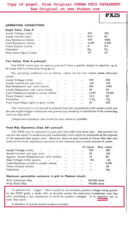
- Warning by OSRAM, from 1925, about sparking tubes
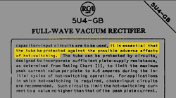
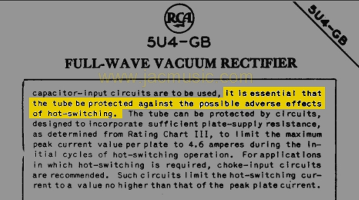
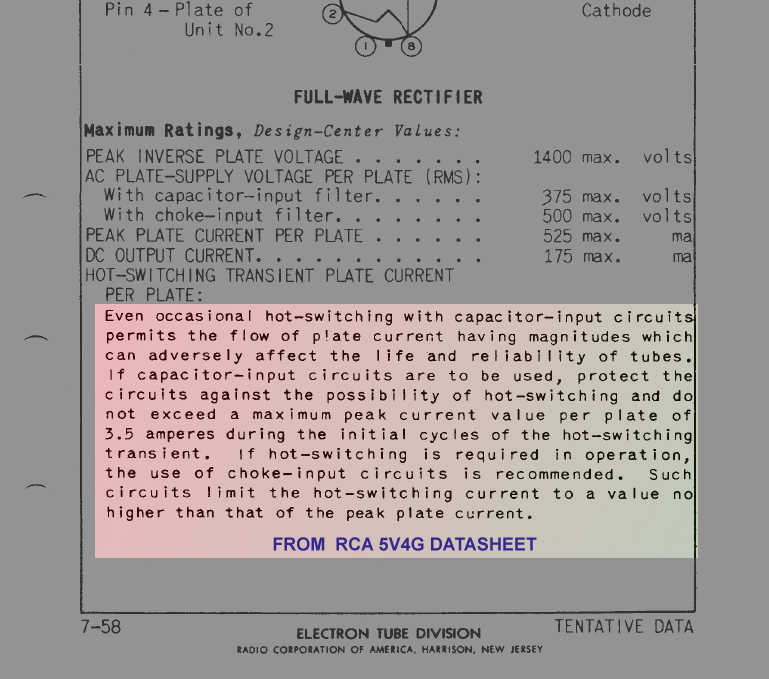
- Warning by RCA for rectifiers, about sparking tubes
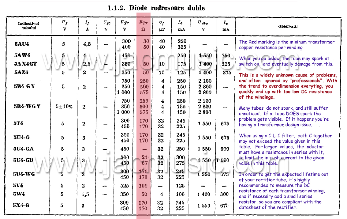
- Table of lowest allowed transformer windings resistance (yes!)
Checklist:
- What peak value do you measure for the grid-to-filament voltage at switch-on or switch-off
- What peak value do you measure for Anode current at switch-on or switch-off?
- DC-coupled circuits need to be measured very carefully for this, they can behave unexpectedly.
- Measure the surge current through the coupling capacitor, to the end-triode. What is the surge current while you switch on and off the amplifier? You will be surprised how high this value can be. This current will flow through ground via the grid-to-ground resistor, and cause a positive voltage there of 50Volt and higher. (The Grid must have a negative voltage ALWAYS)
The following are very useful items, which can SOLVE and PREVENT problems. You are a happy designer when you already tested your tube amplifier for all of this, but perhaps one of this points may be helpful to you still. Who knows!
What can you do if an output tube is sparking?
- Measurements protect you from your own errors. So, don't avoid measurements. Better do a few more than you intended. The reason is very simple: If you would have known, you would not have made the error! You can only find such errors, by measuring everything. This means also the things you thought you didn't need to measure, because you expected them to be good anyway. Here is one typical verbal conclusion, no real engineer will accept: '.... I tried tubes of several brands, and they all work fine, and SO I can see the amplifier has no problem...'. Another typical verbal conclusion is: '....The problem is linked to one tube of a pair, therefore it is the tube, and SO the amplifier is ok....'. Well, perhaps yes. And perhaps no. In fact, you just don't know, and you're comfortably bypassing measurements. The real answer can ONLY come from measurements. Is the amplifier OK, then it will pass the following tests:
- Disconnect the coupling capacitor to the end tubes. If the spark is gone now, you have at least localized one design error.
- A standby circuit sometimes solves the problem, but... when made wrong can also be the cause of unexpected, hard to understand problems. Don't even think of using a standby circuit, when you have no good way to measure surge currents that may result from it. You try to do something good, but may be doing something very bad to the tubes.
- Over driving DHT power triodes is definitely not allowed. Will the amplifier allow for excessive overdrive with the volume at maximum? If yes, this is an elementary design mistake, and you need to correct this. Overdrive must occur in the driver stages first. So the end tube is not in an overdrive condition yet, while the driver stage starts to clip or distort. This allows the user to reach the overdrive level, and effectively not overdrive the end tube.
- Reduce the grid-to-ground resistor to the data sheet value. 2 Mega Ohm is fine for miniature tubes, but not a good value for a 300B tube. A low enough grid-to-ground resistor will protect against the coupling capacitor surge current. At switch on, the voltage across the coupling capacitor is zero, and then this large capacitor gets charged within a fraction of second. Charging a capacitor will make a DC current flow through the grid-to-ground resistor. When this resistor is too high value, POSITIVE Control Grid Voltage results from it. The tube will now try to produce the absolute maximum Anode current it can do, and at high enough Anode voltage that will (of course) give a spark in the tube. The better quality the tube is, and the newer it is, the higher the chances on a spark. This is why we specify limits to the grid-to-ground resistor. What counts is the R x C product, so also read the next paragraph.
- Change the coupling capacitor to the smallest value you need for good frequency response. Oversized coupling capacitors are the number one problem makers for DIY, but also professionals make this mistake often. It can damage DHT tubes. Calculate the correct value, and verify it by a measurement. The coupling capacitor to the end tube is where you need to limit the low frequency response of the amplifier. Do not oversize this capacitor, and leave it up to the transformer in a natural way to limit the low frequency response. Whatever you do, always measure the peak-current in the end tube at switch on. Perhaps you will be surprised how large it is. (And again. we have the maximum value for that in the data sheet).
- A grid series resistor can partially help to reduce the Anode peak current at switch on. This resistor will give an RF frequency roll off, which is why designers put it in. It prevents ringing, and also it reduces interference from radio stations. This is why you see this resistor in professional designs. What you can do for HiFi is choose the resistor low enough to get a frequency roll off outside the audio range, but choose it high enough to limit the grid surge current (into the grid, via the coupling capacitor). The R x C product here is coming from: Series resistor value, and tube grid capacity multiplied by tube open loop gain. (For Miller effect). So the value must be chosen with brains. Not just take 'some' value that you see in other circuits. Often these people just copied it also from another design, and so on. Measure what the resistor does. Where does it make the roll of start? When at 10Mhz, it's useless and wrong chosen. When at 30kHz/ 3dB, it's too close to the audio range of course.
- Please Calculate your designs, and verify it by measurements, and measure the switch-on surge current, and also the switch-off surge current. Measure systematically everything. Trial-and-error designs are one thing, but if you don't at least measure the results of what you produced, you don't know what the circuits really does! You may be heading for defective tubes without knowing it, and when it does happen, not realize where it comes from.
Checklist for the amplifier:
- What peak value do you measure for the grid-to-filament voltage at switch-on or switch-off ?
- What peak value do you measure for Anode current at switch-on or switch-off ?
- DC-coupled circuits need to be checked very carefully for this, they can behave unexpectedly
- Measure the surge current through the coupling capacitor, to the end-triode. What is the surge current while you switch on and off the amplifier? You will be surprised how high this value can be. This current will flow through ground via the grid-to-ground resistor, and cause a positive voltage there of 50Volt and higher. (Grids are supposed to have a negative voltage...)
- Since you must count with people over driving your amplifier even if you warn for it. Make sure the over driving and limiting takes place in the driver tube, and not in the end tube. This gives good protection to the end tube.
What can you do if a rectifier tube is sparking?
- Measure the peak current, and verify it against the data sheet. Remember the derating curves have to be used. If not, the tube may develop a problem later.
- Check if the HV windings of the transformer do not have too low DC resistance. This is a widely unknown specification, but it exist for ALL rectifiers! If the resistance is too low, add a series resistor. Do not blindly trust transformers made by 'manufacturers'. We have seen so many errors with this already. In many amplifiers you can measure this directly from the tube socket when you take out the rectifier, as the AC windings are normally directly connected to the tube socket. Check the schematic first. Please read this - And this also .
- Make sure the Anode current is NOT higher than normal during the start-up moment of the tube, specially not at a moment where the filament voltage is lower than normal. Please measure this, instead of guessing it.
- For the peak current during start up, be aware that with a C-L-C filter, capacitors C1 and C2 are in parallel, because the choke is often working at the start up moment. The choke is often saturated during that short moment, and the very moment it does, it becomes a copper wire only. Add a series resistor in the choke circuit, to prevent problems like this. Measure it, with a scope is the only good way, and you may be surprised of what you see. Most specially here, we say: Measure it. Do not try to replace a measurement by verbal logic.
- Whatever you do, make sure the capacitors of the power supply are empty when you switch on the amplifier. Good practice design rules say, capacitors should be below 40 Volts, 20 Seconds after the amplifier is switched off. Checking this is a very wise idea. If your are above 40Volts, your amplifier is not build by good safety standards. So you need to add a bleeder resistor. Then, after switching off the amplifier, wait 1 Minute before switching on, and most likely your 'spark problem' is cured, indicating as always, this is an amplifier problem and not a tube problem.