AN-02. Circuit topology for tube power supply.
Introduction
The rectifier circuit is the most under estimated part of a tube amplifier. I think that is because exceeding data sheet limits doesn't seem to do any harm. For some designers that is good enough, and some even think the data sheets are wrong. However, rectifier tubes will suffer when peak current is too high. The tube will loose emission, and once that happens, the tube will develop higher forward voltage. In that case, the tubes develops more heat, and eventually too much heat, and a self destroy process begins. How long will it take before that happens? That is hard to say, but it may take 1000 hours. The question for me is not so much how long it takes. Better is to know what we must do, to prevent damage, and gain a multiple tube life.
Why this is done wrong often
The problem with this is, a measurement of the peak current of the rectifier is needed, which requires an oscilloscope. Also use the derating diagrams from the tube data sheet. (see notes at the page bottom). We know, these are two things people try to avoid. Then, just knock something together seems to work most of the time, and people don't spend any more time on it.
The KEY thing however is the peak current. If not using an oscilloscope, at least keep a safe distance from data sheet maximum limits, and use the derating curves.
Even JJ, who publishes data sheets with as little as data as possible, publishes derating curves for the 5U4GB, using a large, and a small capacitor. That should be a clear sign, this is important.
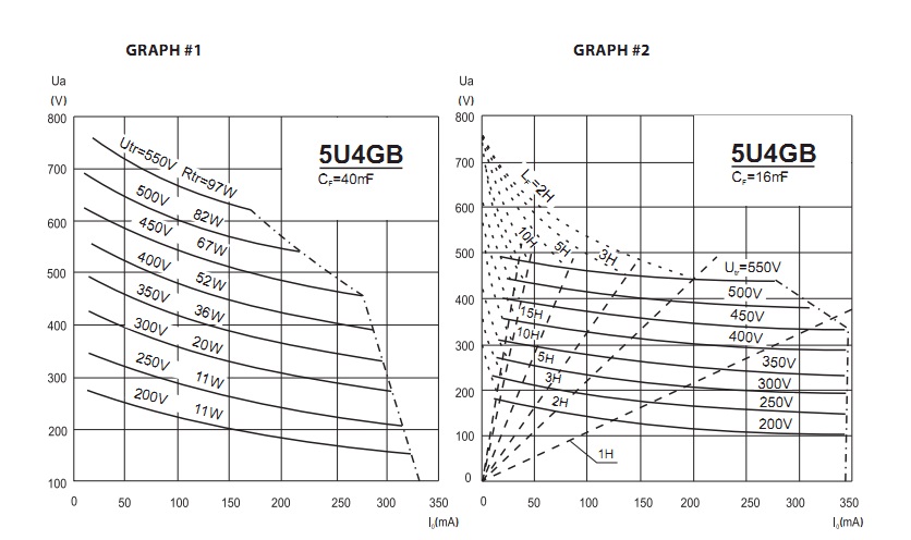
Above is a cut out from JJ data sheet 5U4GB
A better data sheet for this is the RCA 5U4G. (But keep apart 5U4G and 5U4GB is specified different). The RCA data sheet is detailed, and yet easy to understand. You can see there, if you want maximum voltage, you can not take maximum current, and vice versa. Do you want the maximum capacitor, that is possible, but not at maximum voltage. You will find the trade offs in there.
Most unfortunately, such considerations are considered difficult to read. The internet is full of schematics, and that is often preferred above reading data sheets. A big risk is, the schematics are made by people with the same attitude, and they considered it a good design when "it works".
Also copying schematics from companies can be a mistake, because this category designers have to reduce costs. They to replace large coils by oversized capacitors, which is a nice money saver. They just let the user replace the rectifier tubes more often.
Some of the most common errors:
- The DC resistance of the transformer Raa winding is an ESSENTIAL part of the circuit design. Any mistake with that, is slowly killing a good rectifier. People are often very surprized this requirement exists at all, or even dispute it. Transformer manufacturers never heard about it anyway. So on the market are many unqualified transformers and amplifiers. Though this is clearly written in every historic tube data sheet. Below here is a table from the "Piotr" bible. It mentions Rtr, which is the minimum required transformer resistance, the tube should see. (measured at the "Raa" ends of the winding). Unless the transformer is specially wound with thinner copper wire, it's resistance (Raa) will be too low. This must be compensated with an additional, external resistor. It's value is: Rtr-Raa.
- Adding 2...5x more than the maximum allowed capacitance as a first capacitor for the rectifier. Just because 'it works', doesn't mean this is not a tube killer. (Also because of the next point)
- Draw excessive surge current from a rectifier tube during cold start. Caused by low cost chokes, which saturate at start up, too big capacitors, or other causes in the amplifier itself, at start up, such as DC coupled tube stages, adjustable bias, and other risky things.
- Combine the above by not measuring peak current, and start up current. Just copy schematics, makes you copy the mistakes too. Just to give the classical warning once more, when you see more than 33uF on a 5U4G, or more than 4uF on a 274B tube, such a schematic is made by an ignorant designer. So this can already by seen from picture files. Whereas transformer Raa Resistance can be measured simple with a low cost multi meter. Yet while peak current is hard to measure, at least you should make a simulation, for instance with 'PSU Designer', which is freeware for DIY, and the best program of it's kind. PSU Designer will work quickly and easy, and simulate peak current with Oscilloscope-like results, at any point of the circuit you select. For the hard core users there is LTSPICE freeware from Analog Devices. Though LTSPICE will take a very long time to understand when you are new to it. You can not see this when using PSU designer, but it is written with LTSPICE.
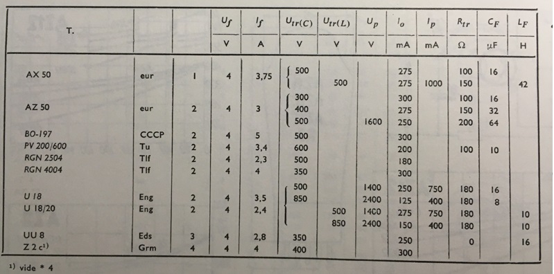
Have a look at the above overview. It's just numbers, but you can extract from this why it is the way it is.
- Let's n do the RGN2504 - RGN4004 compare. Now both tubes are sold for crazy prices on Ebay, specially the RGN4004 if NOS goes above 2000 Euro. Why is that? Well people see in the data sheet it can supply 300mA. So many of the larger amplifiers can be build with the tube. Whereas the "weaker" RGN2505 can supply only 180mA. It is goes somewhere between 1000 and 2000 Euro. What is behind these specifications? When looking at the output voltage, we see RGN2504 is the winner. It is just RGN4004 is a low voltage, high current tube, and RGN2505 is the opposite.
- Transformer DC resistance. There is no rectifier which has no specifications for this. Look for this at AZ50. Which is by itself not better than RGN4004, only it has only a better qualified set of data. Here, Philips brings the transformer resistance (Rtr) in relation to the trade off between maximum current and maximum voltage. You can see AZ50 can almost do the 300mA/350V of the RGN4004. But it even exceeds the 500V/180mA of the RGN2504. How is that magic done? Can only tube really combine this? Yes it can when you pay attention to the transformer Rtr. So at low Rtr, 100Ohms you can go to 300mA. But for 500V (to prevent sparking) you need 200 Ohms Rt, which is less of a problem at 500V, because current is lower here anyway, and Rtr loss is lower too.
Do not treat tube diodes like solid state diodes.
To give you some sensitivity for this item, take note of this elementary difference between tubes and solid state. Solid state devices can easily handle high current. Even the smallest transistors can do a few hundred mA. But when it comes to high voltage, that becomes a lot more difficult. Use them just above maximum voltage, and you will see a defect soon. With tubes, it is reversed. It is difficult to build tubes for high current, but high voltage was never a problem. Use them above maximum voltage seldom gives a problem. Many times the limiting factor is only the socket. But do not use tubes at maximum current, or they won't last very long. So we have to realize, what are the en stressing exactly this natural limit, and design considerations are opposite. So it t would be wrong to treat vacuum diodes and solid state diodes the same way. With tubes, continuous use at peak current will results in much reduced lifetime, but for solid state that is no problem at all.
Good designers will measure peak current with a good instrument, or alternatively over dimension the ratings. This is in order to stay safely away from the damaging limits.
We can not compress a design chapter in just a few pages here. However, keep these elementary things in mind, to get good tube lifetime:
- Use exactly the right heater voltage. Each single percent too high or too low, will cost life time.
- Respect the maximum first capacitor value in the datasheet
- If you use one maximum factor, you should not use another one in addition. Like when you have the maximum current, do not use a maximum first capacitor.
- Understand and apply the derating curves, meaning at maximum current, you can not use the maximum voltage, and vice versa.
- Take care of the Rtr specification.
- Do not use a rectifier a high voltage switch, by switching on and off the heater.
Low residual hum
With a solid state power supply, the last final bit of hum can be eliminated by using larger capacitors. This is no problem for the diodes, as these can take very high peak current. With a tube power supply, the last final bit of hum, is not present because capacitors are too small, but because the choke is too small. In general, a low voltage power supply needs large capacitors and (if used) chokes only with as much inductance as needed. Reason for the small inductance is to avoid voltage drop. A high voltage power supply uses no larger capacitors as needed, and chokes with as much as possible inductance. Reason for the small capacitors is to avoid peak current. While 10 Volts drop across the inductance is no issue for a 400V power supply.
If there is hum, you would be tempted to tweak components values, but better would be to use an improved circuit, if the problem is the circuit itself. The most commonly used circuit is Circuit #1, as below here, but this is a source for grounding errors. In many cases, simply use circuit #2 already brings an improvement. We call this 'star grounding'. Though Circuit#2 is far from ideal, and Circuit #4 does the same even better and with less wiring. Circuit #3 shows one of those typical little things, you can observe when somebody does not treat a tube like a solid state diode. This makes sure the left side of the tube heater wire has the same current (and the same temperature by that) as the right side of the heater wire. Whereas Circuit #4 is such a logical and easy thing to do, but people do not understand why, and take Circuit #1, this is really painful. It is allowed to use Circuit #4, also if you do not understand why it is better, as it is free of patent rights. The words are: No ground loop risk, and electrical stray field. Circuit #5 is the ultimate circuit. Only possible with Lundahl chokes. This is the most beneficial circuit ever, for lowest hum. The choke is not only used here as an inductor, but also creates inductive decoupling of the complete rectifier parts from the amplifier circuit. There is no direct connection any more! All hum signals, no matter how they try to flow, must pass a choke now. Please also read the short explanations on the right, below here. After that I hope you understand why we say it is so silly to find Circuit #1 in most 'professional' designs.
Some circuits
The higher the number, the better the circuit. More text explanation is below here.
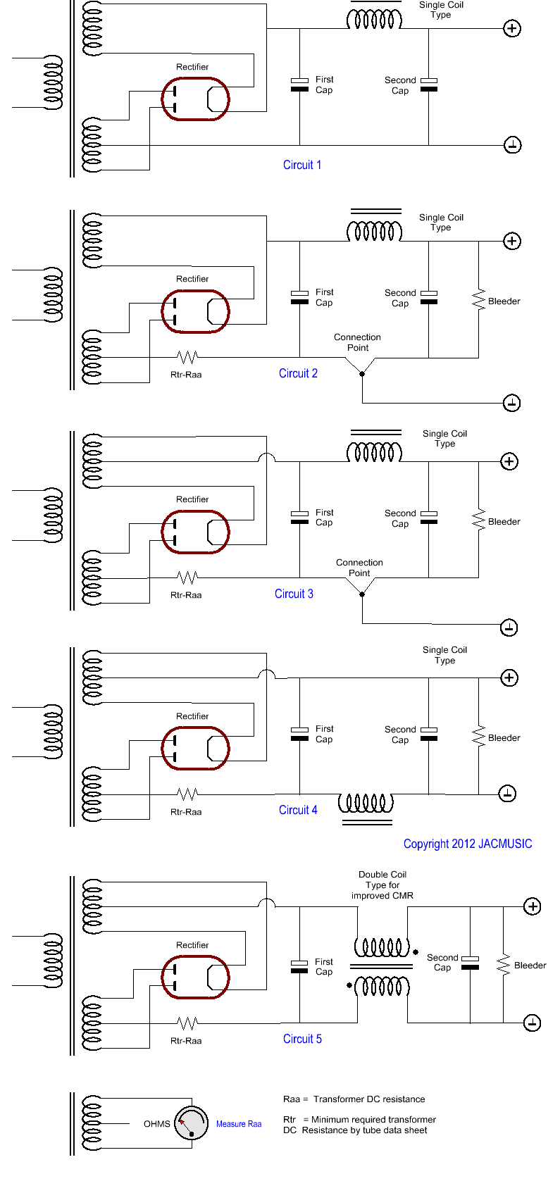
Circuit 1: This is the most commonly used. What is not so nice about this circuit, will get clearer when you understand the benefits of the other circuits here.
Design Quality of Circuit1: One Star *
Circuit 2: Added here is a bleeder resistor, a ground connection point, and if needed an external windings resistor. The ground connection point prevents any faulty ground path. This is called 'star' grounding.
Design Quality of Circuit 2: Two Stars **
Circuit 3: This avoids the rectified DC current flows through the transformer heater winding. This will reduce Transformer hum. However circuit #4 is more simplified and will do the same.
Design Quality of Circuit 3: Three Stars ***
Circuit 4: This circuit refers the Choke AC and DC electrical field to ground, where they can cause less problems. Also the ground path for the first capacitor is now forced in a correct way, same as in circuit 3.
Design Quality of Circuit 4: Four Stars ****
Circuit 5: This is how to connect a double coil Choke, such as the Lundahl LL1673 or similar products. Beware the polarity of the connections. (the dots in the circuit diagram here). The importance of this circuit is very high. We have complete inductive separation of the transformer from the amplifier. Definitely, the transformer capacitance from primary to secondary can not inject an AC hum current into the amplifier any more.
Design Quality of Circuit 5: Five Stars *****
Plate current and Peak current:
Using a true RMS multi meter, with the circuits 2 and 3, the plate current can be measured, via the voltage across the resistor called: Raa-Rtr. Also, with a simple one-channel oscilloscope, the waveform can be made visible. You will be surprized how sharp the current peaks can be, especially at switch on.
For circuits 4 and 5, you need a two channel oscilloscope, and measure the voltage difference across Raa-Rtr, with a differential measurement.
With circuits 2..4, and a battery operated multi meter, you can also measure the RMS voltage across Raa-Rtr.
Bleeder resistor
This device is needed to empty all capacitors after power off. Using no bleeder resistor is safety issue, as voltage may stay on the capacitors for a long time. Also use of no bleeder is a reason for a rectifier sparking sometimes, but not always. This is also rectifier dependent, and a fresh replaced rectifier has a larger tendency for this. What happens? At a repeated switch on, with partially charged capacitor, the rectifier circuit have a short resonance. So this sweeps up the voltage, way over the maximum value, and the rectifier shorts with a spark. So to make sure the capacitors are empty before (repeated) switch on, the bleeder has it's usual function. In addition it is a safety for the repair man, because within one minute after switch on, there may be no voltage anywhere above 40V. Do not mount the bleeder directly on a capacitor, because bleeders get warm, this heats the capacitor, which makes it age too fast. .
Summary
These rules above, are needed to achieve good tube life, and failure free operation. For maximum lifetime of any object, and sure for electron tubes, keep some distance from maximum limits. That is: maximum capacitor value, maximum voltage, maximum current, and minimum copper resistance.
Notes.
Peak current is the killing factors for a tube rectifier. First, there is the cold start up peak current. That can be 0.5 to 2 seconds, in which the amplifier and empty capacitors draw a multiple of normal current, doing so when the rectifier is barely working, and the wear out this moment is equivalent or larger than the whole rest of the session. The second factor is continuous peak current, so when the amplifier has warmed up. The way to measure this is by using a current probe, or by inserting a small resistor in the tube circuit, and make differential voltage measurement across it, using two probe tips.