Doing measurements on the 45 tube.
Description
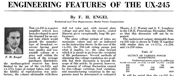
I was pointed out this interesting document in al old radio magazine, by one of our buyers of 45 tubes. The writer of this 1929 article, Francis H. Engel, from Technical & Test Dept. of Radio Victor, which company was integrated in RCA in 1929. He has written quite a few published documents for RCA, about measurements and standardisation.
Well it is now 92 year ago, this article was written, it is bit late to write a reaction to it, but I will do so anyway. From his picture, the writer looks in his late 30's, so he was born somewhere around 1895. As a boy he must have been quite impressed by the dazzling speed at which electronics developed at that time. He must have seen his father replacing the oil lamps in the house by the first Edison electric lamps. So perhaps we think today things develop fast? Well around 1920, I think it went even faster, because there was one break through after the other. in 1890 people went to work on a horse back, in 1910 first airplanes were flying, and in 1920 good quality electron tubes were made.
So here we are reading what Mr. Engel had to say about the 45 tube, just a few months before he was to become an RCA employee in 1929. He comes quickly to the point, and tells what are common problems at the time, and how to overcome these. As you can see, nothing much changed in 100 years of good tube design and good circuit design. Specially with this in mind, I like to read such messages from the past. He writes about gas, heater voltage, changes in mains voltage, signal distortion, output power and more common items.
Before, perhaps read this:
Grid Current of NOS 45. Unfortunately this is a large problem. It can offset the bias of the tube at fully unexpected moments. This will glow the tube anode red, and the amplifier fuse will blow. Sometimes this gives a terrible crack noise, when at the same time a chip of the cathode gets blown off, and gets scattered to fine powder, in the stream of electrons. This power gets vaporized, and for a short moment there is gas in the tube, which causes a spark, which is like a short. Though the spark is not by two electrodes touching, it only looks like that, but in reality, the gas ignites, due to negative resistance. Right after that, the metals of the vapor land on the grid, and seemingly, the tube works again. However the grid is now contaminated, and problems get worse.
Such a short may destroy the tweeter or the Output Transformer. So testing for grid current should give a flawless result. Any "still acceptable" tube is a product which has already degraded half way, and it will break down one day or another, with or without catastrophic effect. Just trying to be clear on this.
Moreover there is no good prediction possible if, or when, and how a tube with small grid current will break down. Anything can occur at a random moment. Once that happened, the tube is bad, and even though it seems to work often after cooling down, it is only an item to sell quickly on Ebay. The problem will come back for sure. Also if it only blew the fuse, that doesn't mean it will do the same next time. It may as well cause a full short the next time. The FULLY WRONG WAY, to test this is with a curve tracer, which is only an impulse tester. Even the worst tube will test fine that way. That is because these CAN NOT measure grid current, but only measure resistive leakage. Which leakage however is seldom a problem. So all of these testers which test the tube without any plate dissipation whatsoever, are fooling the user by measuring resistive leakage and call that grid current. In the exceptional case, when even a cold tube has indeed grid current, then the tube is gassy instead. This also causes grid current, but here we talk about a broken tube, which will not even play in the amplifier. I have said this a few time before, but this feels sometimes like trying to sell refrigerators to Eskimos.
Still it is like this: To judge grid current requires the the heated at maximum allowed anode heat for minimum 5 minutes, and then large signal on the grid. Do you have no grid current like that? Only then the tube is proven good. Even the often used AT1000 tester, can not really do it. It can warm up the tube, and it can test grid current, but due to software foolishness, not simultaneously. And no, doing it separate makes again bad tube pass. So do it as your grandfather, put a uA meter in series with the grid, bias the tube for 5 minutes, and you will see a terrible difference with any impulse tester and even AT1000.
250V Specified 45 tubes. One thing I would like to point out here, in the first days of radio, there was a trend to have 180V or 250V DC working voltage for the whole radio. Now that is not so ideal for larger DHT, of which the 45 is one of the first family members which is a little bit larger. So very old articles will often use 250V, and as you can read here, Mr. Engel even worked with 180V. In order to get the maximum power out of the tube, later versions had higher anode voltage allowed. Note, earlier 45 tubes did NOT have this 275V option. They may not have been build for it, and sure they were not tested for it. As this 275V came in silently, there is no marking on a "250V only" tube, if it is one like that. You simply can not know.
So a tube which is "just ok" at 250V, may test bad at 275V. This is indeed always an issue with the older types. So they may develop grid current at 275V and full dissipation, and self destroy.
At EML we increased the voltage capability, our 45 can do 300V. The later 45B can even do more than 400V.
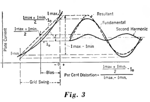
Distortion. In this article. Mr. Engel refers to "Radio Broadcast" magazine from 1929, page 329, for what he found was an extremely good way to estimate the maximum output power at maximum 5% 2nd. Harmonics distortion. The article is by an employee of Westinghouse tube company. This number of 5% is still use today. I was able to find this article in the internet, and yes it's really interesting to read. This method is clever and easy to perform.